Vertiv | Liebert
®
Large System Installation Manual | 49
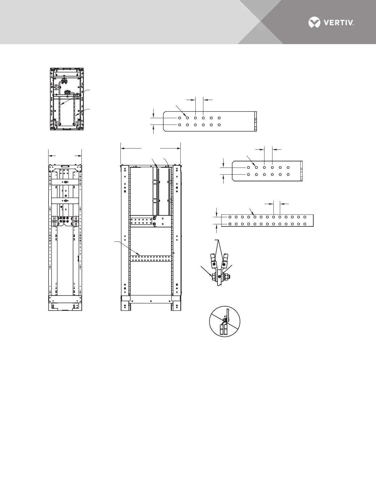
Figure 42 Terminal details—Liebert® stand-alone 17" 800-1200kVA junction cabinet
TOP
Front
FRONT
RIGHT SIDE
BPP12203
Pg. 2, Rev. 3
1. 24" (610mm) minimum clearance required above the unit.
2. Keep the cabinet within 15 degrees of vertical.
3. Top and bottom cable entry is available through
removable conduit plates.
4. Control wiring and power wiring must be run in
separate conduit.
5. All wiring must be in accordance with national and
local electrical codes.
Negative Bus (-)
See Detail
Positive Bus (+)
See Detail
Front
1.74" (44mm)
1.74" (44mm)
1.74" (44mm)
Ø 0.56
(14mm)
Ø 0.56
(14mm)
Ø 0.56
(14mm)
2" (50mm)
Typical
2" (50mm)
Typical
1.57" (40mm)
Typical
NEGATIVE BUS DETAIL
POSITIVE BUS DETAIL
GROUND BUS DETAIL
Ground Bus
See Detail
(+) (-)
DO NOT DOUBLE-STACK LUGS
(two lugs on same side of busbar).
This is to prevent the cables from
contacting other busbars.
DUAL LUG
CONNECTION DETAIL
Lugs
Busbar
Bolt
CB1-3
CB1-3
17-1/2"
(444mm)
33-1/2"
(850mm)
A junction cabinet is required
for Liebert® NXL™ units rated
500kVA and above except for
stand-alone individual battery

 Loading...