2. Check Fuses. If fuses are blown, perform the following:
• Check resistances across the phases at the Mains connector and note them in the
following table.
NOTE: Power wires must be removed from the motor for resistance test.
L1 - L2 Ohm
L2 - L3 Ohm
L1 - L3 Ohm
• Resistances should be similar for all 3 readings.
• Resistance readings should be greater than 100kOhm.
• Check all connections. Make sure connections are on the wire strand and not on
the wire insulation.
• Replace Fuses.
• Check mains voltage at each phase (phase to ground) at the Mains connector.
Confirms phase failure not present.
• Check that the voltage is within the acceptable voltage range at the Mains
connector. Confirmsline under-voltage is not present.
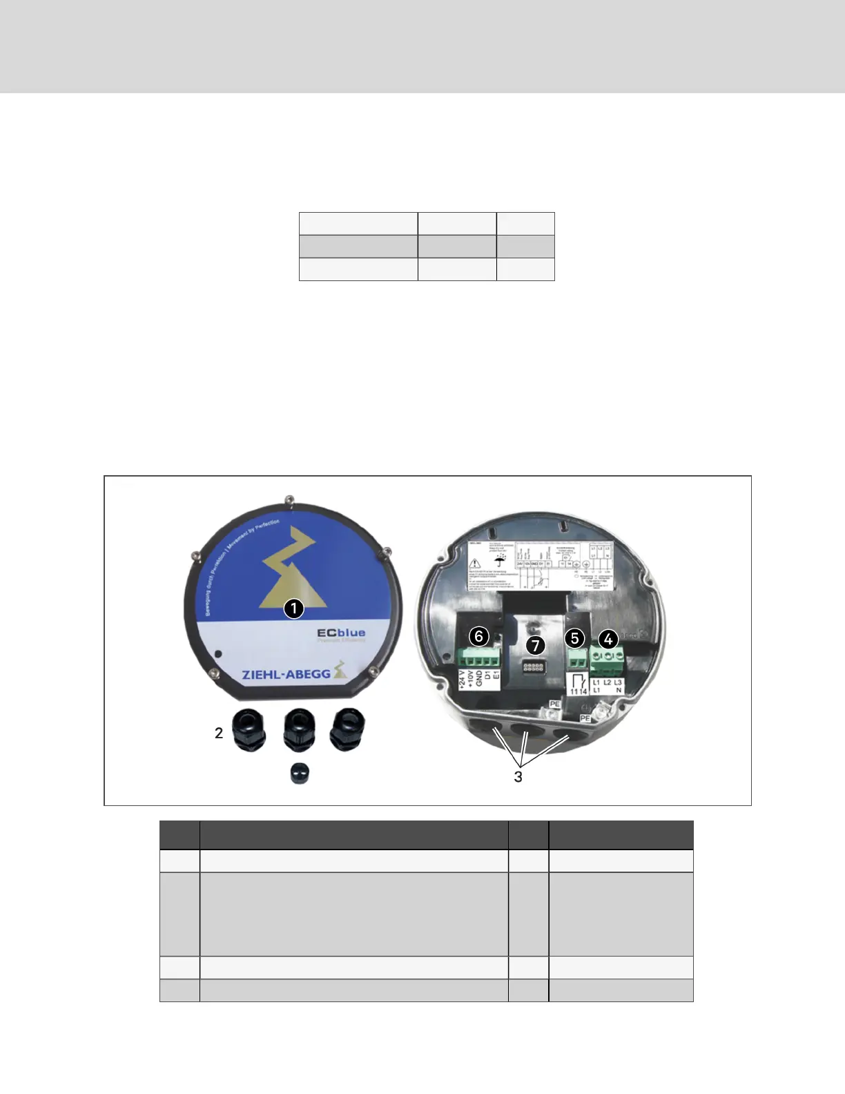
Figure 9.1 EC-fan Connections
Item Description Item Description
1 Cover of controller housing 5 Alarm-relay connection
2
Cable glands and seal insert for two cables (if needed)
• Motor size "D": 3xM16 and 1xseal insert with
two 5-mm holes.
• Motor size "G": 3xM20 and 1x seal insert with
two 6-mm holes.
6 Control-system connection
3 Cable-entry points with plastic fastener 7 Slot for add-on module
4 Mains connection
Vertiv | Liebert® Mini-Mate™ Installer/User Guide
40