Electrical service is required for all models. All power and control wiring and ground connections must be
in accordance with the National Electrical Code and local codes. Refer to the equipment serial-tag data
for electrical requirements.
A field-supplied, manual, electrical-disconnect switch should be installed in accordance with local codes
and distribution system. Consult local codes for external disconnect requirements.
NOTE: Input-power requirements: For 3-phase units, only 3 power wires and an earth ground are
required.
Each unit is shipped from the factory with internal wiring completed. Refer to the electrical schematic
when making connections.
The electrical connections are described in the submittal documents included in the Submittal Drawings
on page35.
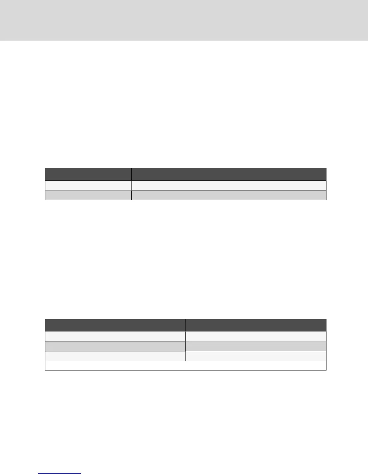
The following table lists the relevant documents by number and title.
Document Number Title
DPN004168 Electrical Field Connections, top discharge
DPN004169 Electrical Field Connections, horizontaldischarge
Table 5.1 Electrical Field-connection Drawings
5.1 Low-voltage, Control Connections
A field-supplied, shielded, 6-wire control connection (24 VAC) is required between the evaporator and the
condensing unit.
Control wiring must be installed in accordance with the National Electrical Code (NEC) Class 1 or Class 2
circuit according to wire-routing conditions chosen and local codes.
Low-voltage wiring should be sized to allow a 1-Volt maximum drop due to line resistance between the
evaporator and condensing unit. Use NEC Class 1 or 2 wiring according to wire routing conditions chosen
and local codes, sizing wire per maximum wire lengths using Table 5.2 below. Connect the shield wire to
earth (ground) at the Liebert® equipment. Avoid running the low-voltage connections near high-voltage
lines or loads such as light ballasts.
NOTE: Do not connect additional electrical devices to the control circuit. The internal control
transformer is only sized for factory-supplied components. Refer to the appropriate submittal
drawings for your system for electrical connections. See Table 5.1 above.
Max. Distance, * ft (m) Min. Wire Gauge, AWG (mm2)
50 (15) 20 (0.75)
100 (30) 18 (1.0)
150 (45) 16 (1.5)
* One-way control wire run between outdoor condensing unit and evaporator.
Table 5.2 Recommended minimum wire size betweenindoorandoutdoorunits
Vertiv | Liebert® PFD™ Installer/User Guide
22