Vertiv | Liebert
®
RX
™
Remote Distribution Cabinet User Manual | 7
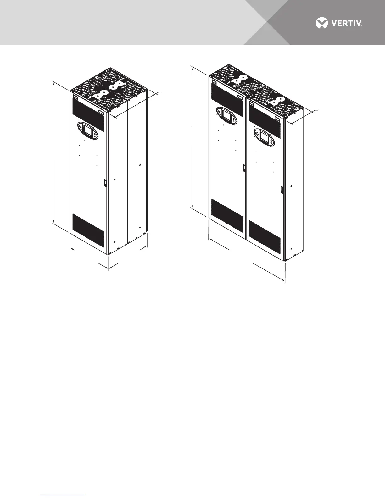
Figure 2 Configuration 2 and Configuration 3—Two Liebert RX units
1.5.4 Configuration 4—Three Units
This three-unit configuration has two units attached back-to-back with a third unit attached to
the side. It is 36" wide and 24" (610mm) deep. These units are free-standing and can be set on a
raised floor. Refer to Figure 3.
1.5.5 Configuration 5—Four Units
This four-unit configuration has two units attached back-to-back with one unit attached to each
side. It is 48" wide and 24" (610mm) deep. These units are free-standing and can be set on a raised
floor. Refer to Figure 3.
RX17000
Rev. 1
CONFIGURATION 3
Side-by-Side
CONFIGURATION 2
Back-to-Back
NOTES:
1. Units are ordered and shipped separately.
Units can be attached in the field as shown.
2. Side-by-side units are not free-standing. They
must be attached to a wall or other support.
Mounting hardware supplied by others.
3. Hardware to attach units to each
other is factory-supplied.
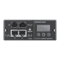
4. Shown with optional monitoring display.
5. Configuration 2 requires front and rear
service access.
12.93"
(328mm)
25.86"
(657mm)
23.75"
(603mm)
23.75"
(603mm)
47.5"
(1207mm)
78.74"
(2000mm)
78.74"
(2000mm)
6. Configuration 3 requires front service access.
7. Service access clearance dimensions:
36" (914mm) for units up to 150V to ground
42" (1067mm) for units over 150V to ground
8. Clearance above the unit for cooling air flow: 18"
(460 mm) minimum
9. Clearance below for cables:12" (305mm)
minimum.