Vertiv | Liebert
®
RX
™
Remote Distribution Cabinet User Manual | ii
FIGURES
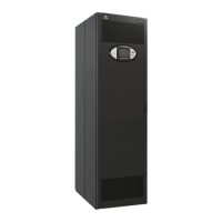
Figure 1 Typical cabinet and floor planning dimension data . . . . . . . . . . . . . . . . . . . . . . . . . . . . . . . . . . 3
Figure 2 Configuration 2 and Configuration 3—Two Liebert RX units . . . . . . . . . . . . . . . . . . . . . . . . . 6
Figure 3 Configuration 4—Three units and Configuration 5—Four units. . . . . . . . . . . . . . . . . . . . . . 7
Figure 4 Input electrical field connection location for units with main panelboard breaker . . . 9
Figure 5 Input electrical field connection location for units without main panelboard breaker.
10
Figure 6 Electrical field connections for units with LDMF monitoring . . . . . . . . . . . . . . . . . . . . . . . . 11
Figure 7 Electrical field connection for units with Current Plus Monitoring . . . . . . . . . . . . . . . . . . 12
Figure 8 Liebert LDMF
™
, Liebert SiteScan
®
and Liebert IntelliSlot
™
location and connection de-
tails13
Figure 9 Current Plus Monitoring adapter board electrical field connections . . . . . . . . . . . . . . . . 15
Figure 10 Electrical field connections for CT Module replacement CTs . . . . . . . . . . . . . . . . . . . . . . . 17
Figure 11 Electrical field connections for Liebert LDMF
™
summary alarm. . . . . . . . . . . . . . . . . . . . . 18
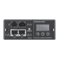
Figure 12 Liebert LDMF local display . . . . . . . . . . . . . . . . . . . . . . . . . . . . . . . . . . . . . . . . . . . . . . . . . . . . . . . . . .25
TABLES
Table 1 Maximum wire range recommended torque values . . . . . . . . . . . . . . . . . . . . . . . . . . . . . . . . .20