Vertiv™ NetSure™ 5100 Series -48 VDC Power System User Manual
Proprietary and Confidential © 2022 Vertiv Group Corp.
15. Enable the external alarms, or notify appropriate personnel that this procedure is finished.
16. Ensure that there are no local or remote alarms active on the system.
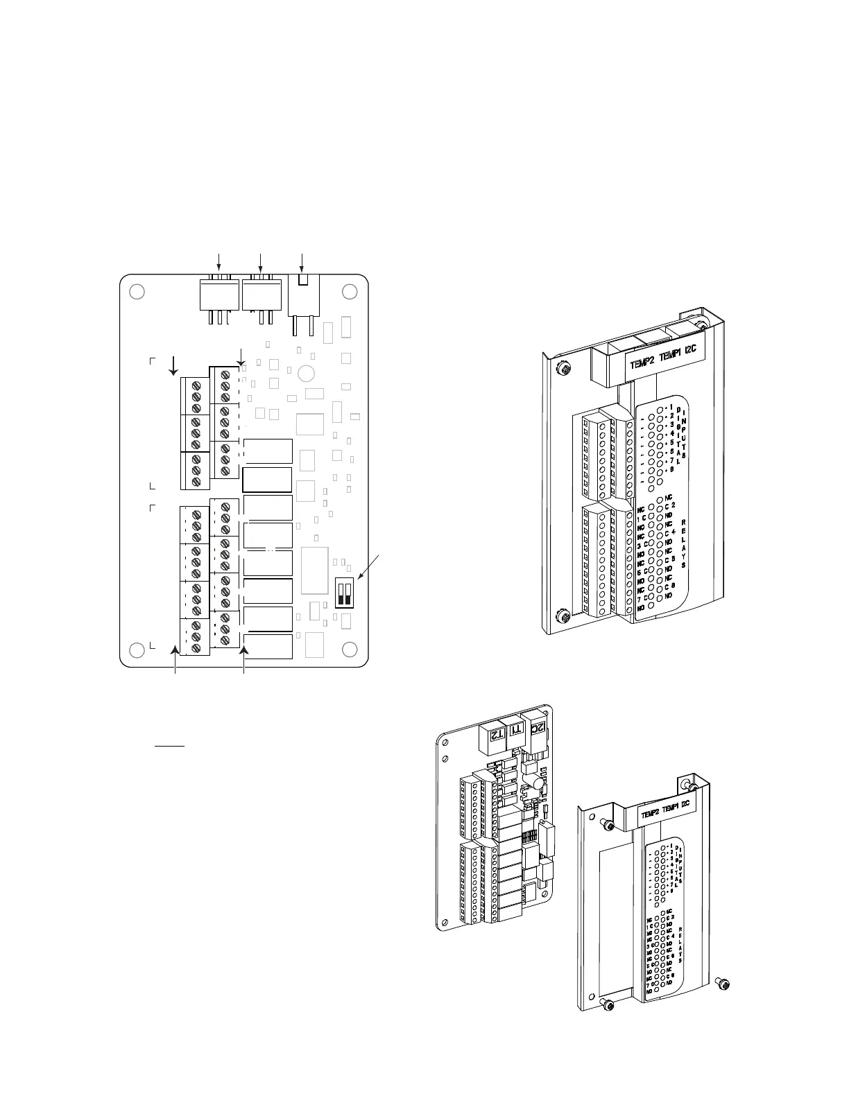
Figure 5.9 Replacing an IB2 (Controller Interface Board) Circuit Card
J3-J9:
Wire Size Capacity: 16 AWG to 26 AWG.
Wire Strip Length: 0.20 inch.
Recommended Torque: 2.2 in-lbs.
IB2 Assembly
IB2 Assembly
(exploded view)
Switch settings
must be in this
position to interface
with the controller.
IB2
(Controller
Interface
Board)
Connector
to Controller
IB2 Temp
Probe 1
IB2 Temp
Probe 2
-
J12
RELAY
SW1
7
J2
J11
5 3
1
Relay Output Terminal Blocks Digital Input Terminal Blocks
J9 J8 J7 J6 J5 J4 J3
8 6 4 2
8 7 6 5 4 3 2 1
+
NO C NC
NO
C
NC
NO C NC
NO
C
NC
NO C NC
NO
C
NC
NO C NC
NO
C
NC
5 3 1
46 2
5 3 1
46 2
5 3 1
46 2
5 3 1
46 2
5 3 1
46 2
5 3 1
46 2
5 3 1
46 2
Relay
No.
Relay
No.
Input
No. (
–
)
Input
No. (+)
8 7 6 5 4 3
2 1
ONOFF
1
2

 Loading...


