Chapter 2 Installation Instruction 7
NetSure 531 A41, NetSure 531 A91 Subrack Power system User Manual
Note:
If the user requires the system to meet the CE certification, install the epoxy board top cover to be installed at a distance of 1.8
meters high above the ground.
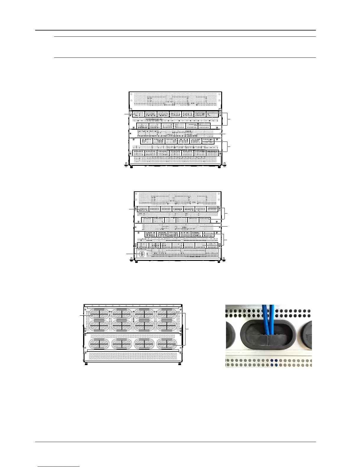
Epoxy board top cover for DU unit cabling:
Cabling from the cable outlet area and then fixed to the cable-bundling plate and the top edge. As shown in the
Figure 2-5.
Cable outlet area
Cable-bundling plate
Cable outlet area
Square unit
Figure 2-5 Cable entry Illustration of the DU unit
Epoxy board top cover for MFU unit cabling is shown in 2-6.
Cable outlet area
Cable-bundling plate
Signal cable
outlet holes
Cable outlet area
Square unit
Figure 2-6 Cable entry Illustration of the MFU unit
Dismantle several square units of the cable outlet area on site according to the actual cable outlet space.
Rubber ring top cover for DU unit cabling:
Use the electrician's knife incise the "+" mark on the rubber unit. As shown in Figure 2-7.
Latex unit
Cable outlet area
Figure 2-7 Cable entry Illustration of the DU unit

 Loading...


