18 Chapter 4 Trouble Shooting
NetSure 531 A41, NetSure 531 A91 Subrack Power system User Manual
1. Check if the alarm is caused by mains failure, if yes, disconnect some loads to prolong the operation of
the whole system.
2. Check the DC under-voltage value set through the controller. If the set value is inappropriate, correct
it.
3. Check if any rectifier is inoperative, or has no output current. If yes, replace it.
4. Check if the total load current exceeds the total rectifier current during float charge. If yes, disconnect
some loads or add more rectifiers to make the total rectifier current bigger than 120% of the total load
current with one redundant rectifier
Load Fuse Alarm,
Batt Fuse Alarm
Check if the corresponding MCB is switched off. If the MCB is open, find out the fault and remove it.
Otherwise, the alarm circuit is faulty. Please contact Vertiv
1. Check if there is mains failure, and the battery voltage is lower than the value of ‘LVD2’.
2. Check whether the battery is disconnected from the system manually
The rectifier with the fault indicator (red) on is faulty.
Power off the rectifier, and then power it on after a while. If the alarm persists, replace the rectifier
Check if the mains voltage is above 530V or under 260V. If the mains voltage is under the AC
under-voltage value or above the AC over-voltage value, the mains grid should be improved
Pull out the rectifier to check if the fan is obstructed. If yes, clean it and push the rectifier back. If the fan
is not obstructed or if the fault persists after cleaning, replace the fan
Check if the communication cable is connected properly between rectifier and controller. If yes, restart
the rectifier. If the alarm persists, replace the rectifier
1. Check if the battery compartment temperature is too high. If yes, cool down the battery compartment.
2. Check if there is battery internal fault. If yes, replace the faulty battery
4.2 Rectifier Fault Handling
The indicator description, fan and handling methods of all the rectifiers on the system are the same.
Alarm handling
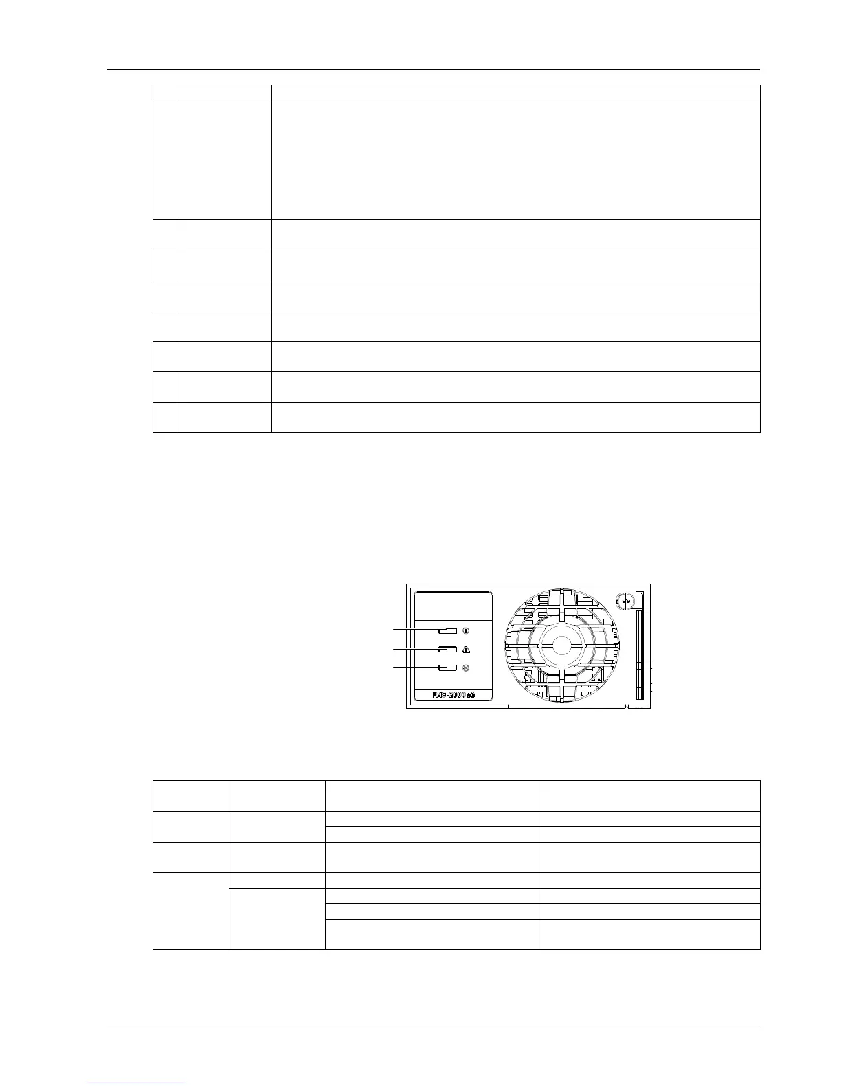
The symptoms of usual rectifier faults include: Run indicator (green) off, Protection indicator (yellow) on, Protection
indicator flash, Fault indicator (red) on and Fault indicator flash, as shown in Figure 4-1.
Power indicator (Green)
Protection indicator (Yellow)
Alarm indicator (Red)
Figure 4-1 Rectifier indicator
The indicators are shown in Table 4-2.
Table 4-2 Indicator fault description
Run indicator
off (green)
Make sure there is input/output voltage
Assistant power source of the rectifier fails
Run indicator
flash(green)
The monitoing module performs operations
upon the rectifier
No actions need to be taken
Protection
indicator on
(yellow)
AC input voltage abnormal
Make sure the AC input voltage is normal
Remove the object that blocks the fan
Ventilation path blocked at the inlet or vent
Remove the object at the inlet or vent
Ambient temperature too high or the inlet too
close to a heat source
Decrease the ambient temperature or remove
the heat source

 Loading...


