Chapter 4 Trouble Shooting 19
NetSure 531 A41, NetSure 531 A91 Subrack Power system User Manual
Protection
indicator on
(yellow)
Current sharing imbalance
Check whether the rectifier communication is
normal. If not, check whether the
communication cable is in normal connection.
If the communication is normal while the
protection indicator is on, replace the rectifier
Power factor compensation internal under
voltage or over voltage
Protection
indicator
flash(yellow)
Rectifier communication interrupted
Check whether the communication cable is in
normal connection
Reset the rectifier. If the protection is triggered
again, replace the rectifier
Two or more recitifiers have the same ID
number
Contact Vertiv for maintenance
Average current of positive and negative
deviations ≤ 1.2A
Check whether the rectifier communication is
normal. If not, check whether the
communication cable is in normal connection.
If the communication is normal while the
protection indicator is on, replace the rectifier
Fault indicator
flash (red)
Replacing R48-2000e3 rectifier
It is recommended not to repair any other parts of the rectifier. When faulty, the rectifier should be replaced, not
repaired. See the following procedures to replace the rectifier.
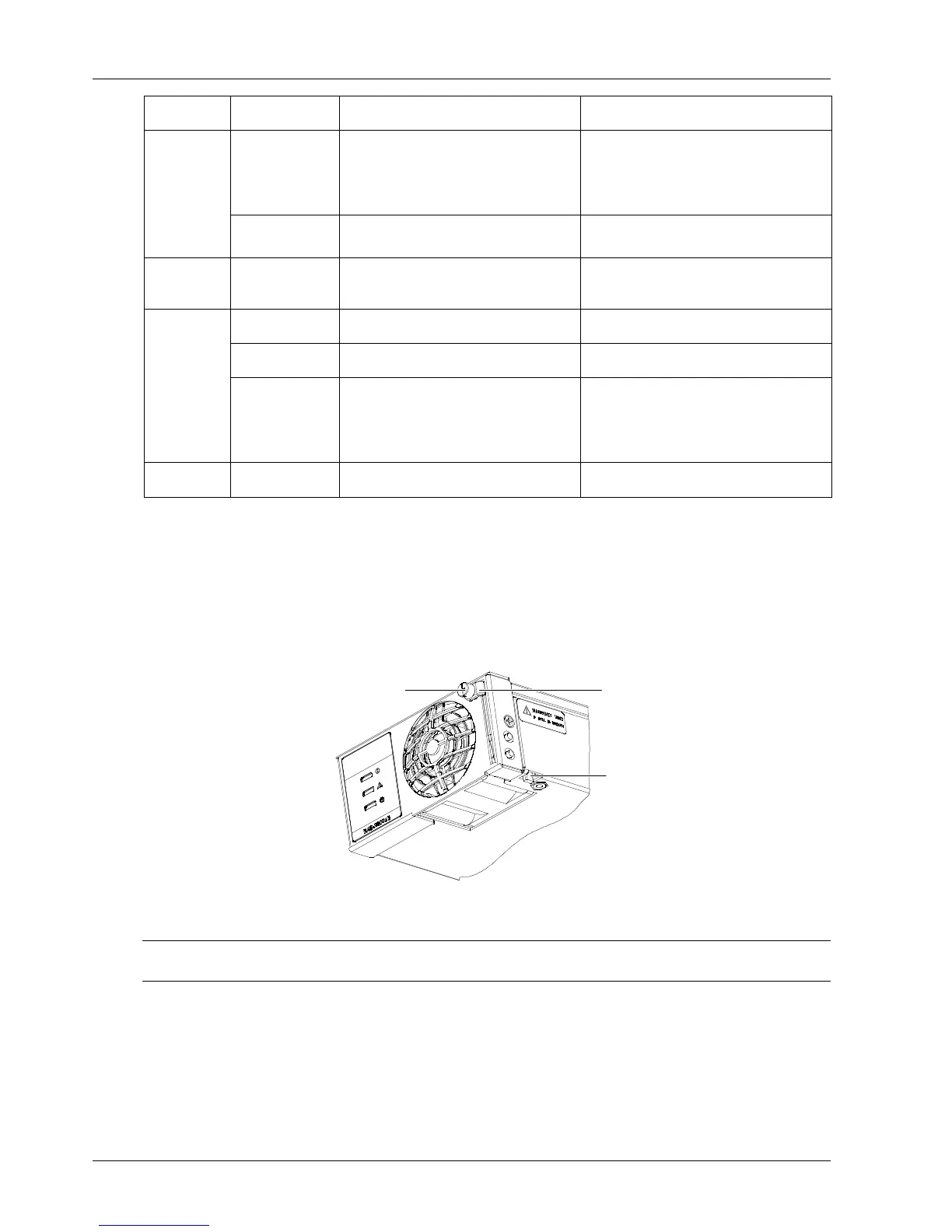
1. Place the Rectifier into an unoccupied mounting slot without sliding it in completely.
2. Loosen the captive fastener securing the top of the latch mechanism to the front of the Rectifier. Pull the top of the
latch mechanism away from the Rectifier (this will retract the latch mechanism located on the underside of the
Rectifier). Refer to Figure 4-2 for latch mechanism illustration.
Figure 4-2 Installing a Rectifier
3. Push the Rectifier completely into the shelf.
Note
Surface temperature of the removed module is still high, hold the module to avoid falling.
4. Push the top of the latch mechanism into the front panel of the Rectifier and secure by tightening the captive
fastener. This locks the Rectifier securely to the shelf.
5. Repeat the above steps for each Rectifier being installed in the system
6. After the Rectifiers are physically installed in the mounting shelf(s), they are ready for operation immediately after
power is supplied to them.
7. Certain functions (i.e. rectifier current limit, rectifier addressing) may require adjustment when adding or replacing a
Rectifier Module. Refer to the Power System documentation for instructions.

 Loading...


