MA455U41
EIB
SH1-
SH1+
SH2-
SH2+
SH3-
SH3+
J5
J6 J7
J8 J9
DCV1
DCV2
DCV3
DCV4
DCV5
DCV6
DCV7
D5_NC
DCV8
D5_COM
D1_NC
D2_NC
D1_COM
D2_COM
D1_NO
D2_NO
D3_NC
D4_NC
D3_COM
D4_COM
D3_NO
D4_NO
J3 1
J3 2
J3 3
J4 1
J4 2
J4 3
2 4 3 1
J2
D5_NO
1 2 3 4 5 6 1 2 3 4 5 6 1 2 3 4 5 6 1 2 3 4 5 6 1 2 3 4 5 6
SHUNT
INPUTS
VOLTAGE
INPUTS
RELAY OUTPUTS
EIB TEMP
PROBE 2
EIB TEMP
PROBE 1
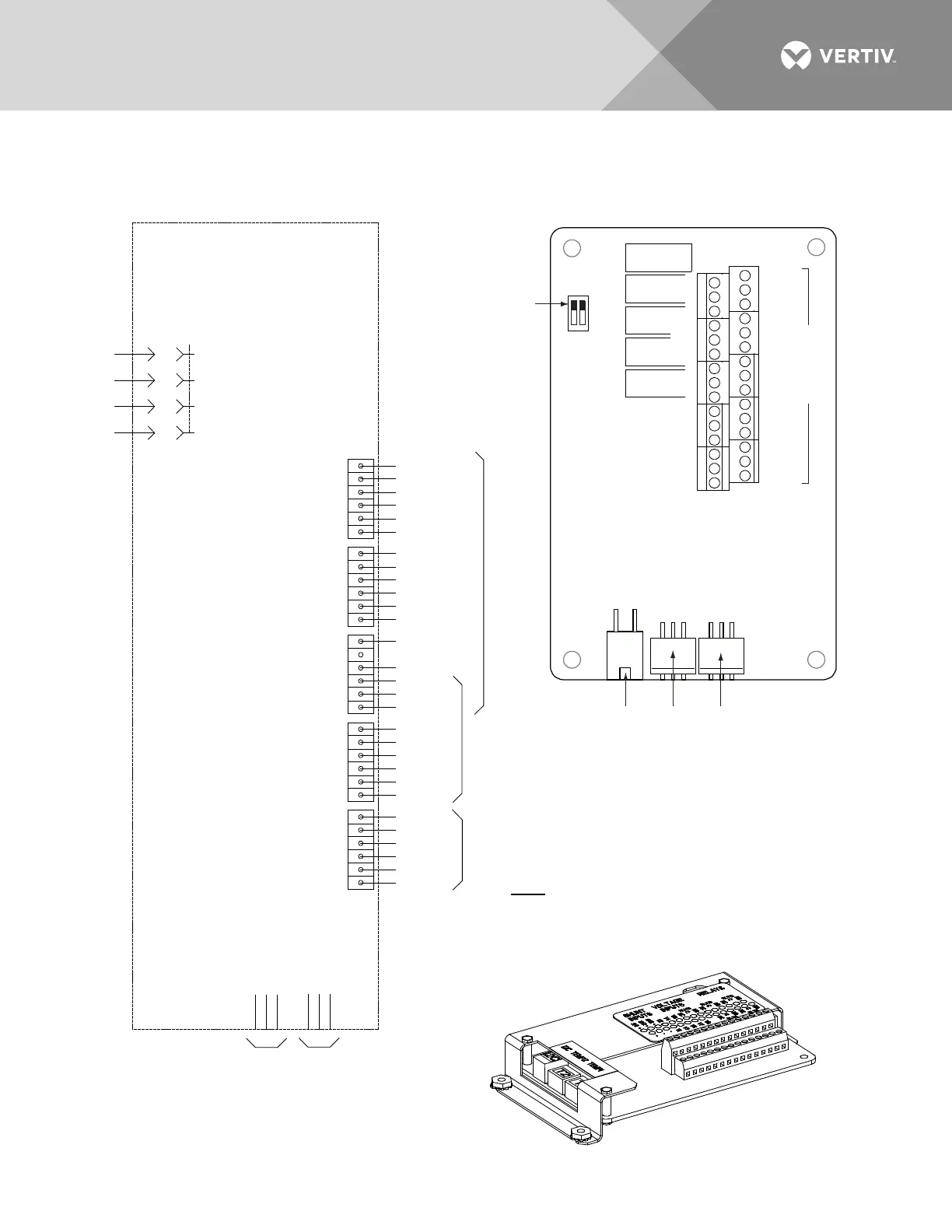
Schematic Diagram of EIB
EIB Assembly
Switch settings must be in this position
to interface with the controller.
J4
SW1
J2
J3
Connector
to Controller
EIB Temp
Probe 2
EIB Temp
Probe 1
J5 J6 J7 J8 J9
2
4
6
31 5
2
4
6
31 5
2
4
6
31 5
2
4
6
31 5
2
4
6
31 5
-
+
Shunt
Inputs
Shunt Inputs
Voltage
Inputs
Voltage Inputs Relays
Sh1
V1
V2
V3 V5 V7 V8
V4 V6
RLY3RLY1
Sh2 Sh3
Sh1 Sh2 Sh3
NOCNC NOCNC NOCNC
NOCNC NOCNC
Relays
RLY5 RLY2 RLY4
Terminal Blocks
ON OFF
1
2
EIB
(Controller Extended Interface Board)
Not all I/O points may be available for customer
connection (some may be used for factory system
connections). Refer to the configuration drawing
(C-drawing) supplied with your system for your
system’s specific configuration.
J5-J9:
Wire Size Capacity: 16 AWG to 26 AWG.
Wire Strip Length: 0.20 inch.
Recommended Torque: 2.2 in-lbs.

 Loading...


