MA4C5U31
IB2
DI1-
DI1+
DI2-
DI2+
DI3-
DI3+
J3
J4
J5
J6
J7
J8
J9
DI4-
DI4+
DI5-
DI5+
DI6-
DI6+
DI7-
DI7+
DI8-
DI8+
DO1_NC
DO2_NC
DO1_COM
DO2_COM
DO1_NO
DO2_NO
DO3_NC
DO4_NC
DO3_COM
DO4_COM
DO3_NO
DO4_NO
DO5_NC
DO6_NC
DO5_COM
DO6_COM
DO5_NO
DO6_NO
DO7_NC
DO8_NC
DO7_COM
DO8_COM
DO7_NO
DO8_NO
J11 1
J11 2
J11 3
J12 1
J12 2
J12 3
2
4
3
1
J2
6 5 4 3 2 1 6 5 4 3 2 1 6 5 4 3 2 1 6 5 4 3 2 1
6 5 4 3 2 1 6 5 4 3 2 1 6 5 4 3 2 1
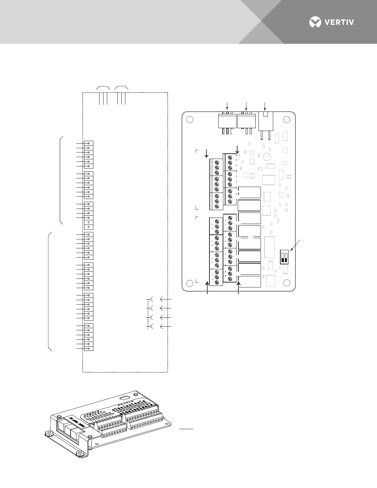
STUPTUOYALER
STUPNILATIGID
Schematic
Diagram
of IB2
IB2 TEMP
PROBE 1
IB2 TEMP
PROBE 2
IB2 Assembly
Switch settings
must be in this
position to interface
with the controller.
IB2
(Controller
Interface
Board)
Connector
to Controller
IB2 Temp
Probe 1
IB2 Temp
Probe 2
-
J12
RELAY
SW1
7
J2
J11
5
3
1
Relay Output Terminal Blocks Digital Input Terminal Blocks
J9
J8 J7 J6
J5 J4 J3
8
6 4
2
8 7 6
5 4 3
2 1
+
NO
C
NC
NO
C NC
NO
C
NC
NO
C NC
NO
C
NC
NO C
NC
NO
C
NC
NO C NC
5
3 1
4
6 2
5
3 1
4
6 2
5
3
1
46
2
5
3
1
46 2
5 3 1
46 2
5 3 1
4
6 2
5
3
1
4
6 2
Relay
No.
Relay
No.
Input
No. (
–
)
Input
No. (+)
8 7 6 5 4 3
2 1
ONOFF
1
2
The controller relay assigned to “Critical Summary” alarm (relay 1
by default) will operate in the “Fail Safe Mode”. “Fail Safe Mode”
means Relay 1 is de-energized during an alarm condition, opening
the contacts between the C and NO terminals, and closing the
contacts between the C and NC terminals.
The controller’s remaining seven (7) relays energize during an
alarm condition, closing the contacts between the C and NO
terminals, and opening the contacts between the C and NC
terminals.
Not all I/O points may be available for customer connection (some
may be used for factory system connections). Refer to the
configuration drawing (C-drawing) supplied with your system for
your system’s specific configuration.
J3-J9:
Wire Size Capacity: 16 AWG to 26 AWG.
Wire Strip Length: 0.20 inch.
Recommended Torque: 2.2 in-lbs.

 Loading...


