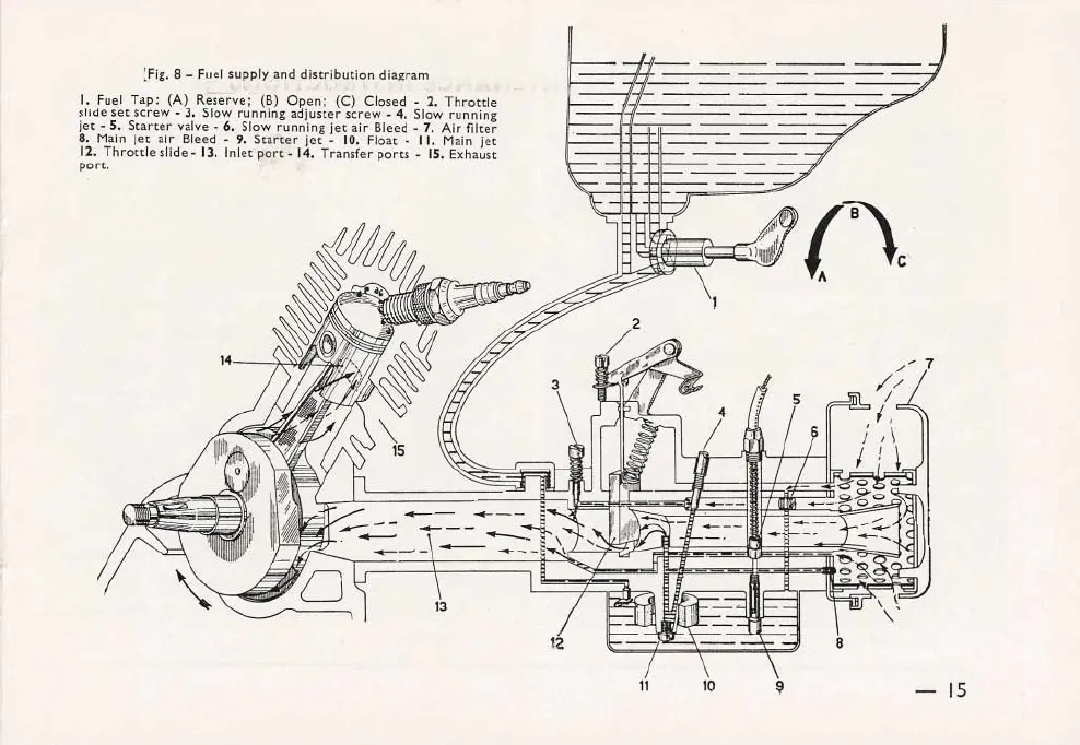
~Fig.8 - Fuel supply_anddistribution diagram
I. Fuel Tap: (A) Reserve; (B) Open; (C) Closed. 2. Throttle
slide set screw. 3. Slow running adjuster screw - 4. Slow running
jet - S. Starter valve - 6. Slow running jet air Bleed - 7. Air filter
8. Main let air Bleed. 9. Starter jet. 10. Float. 11. Main jet
12. Throttle slide. 13. Inlet port. 14. Transfer ports. 15. Exhaust
port.
14
7
8
11 10
- 15
 Loading...