54 400202.01
vetus®Installation manual VF4 VF5
5.3.10 Installation of power supply
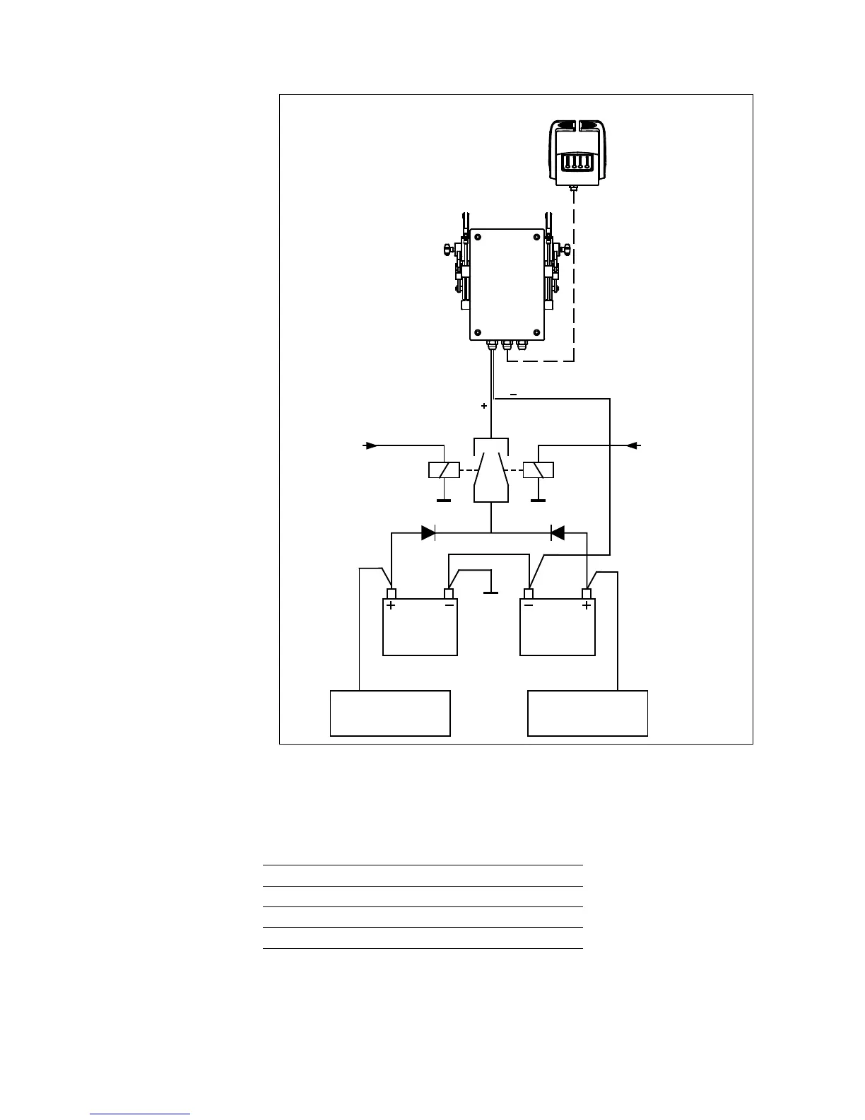
Starter motors: the cables
that run from the battery to
the starter motors must have
a cross-section of at least
50 mm
2
(AWG 0)(both the
plus and the minus cable).
Electrical installation: the
earth poles of the batteries
must be connected with a
cable with a cross-section
of at least 50 mm
2
. (AWG 0)
The earth line from the con-
trol box must come directly
from the batteries.
Control box: each control
box must be powered by the
batteries. The power cables
(plus) must be fitted with a
10 A decoupling diode.
In this way the control
box is always powered by
the battery which is high-
est charged. The minimum
cross-section for the cable is
2.5 mm
2
(AWG 12).
‘R1’ is a relay that is acti-
vated by the key of the port
engine, while ‘R2’ is a relay
that is activated by the key of
the starboard engine.
5.3.11 Power supply
The system works on 12 V battery power supply. The table gives the breaking current for the fuses used to
protect the electronic cards in the control box.
Voltage 12 V
Internal fuse (on card) 3.15 A
Fuse in panel 6.15 A
No load current t 0.5 A
COM M AN D
ENG IN E 2
WAR M /S
ENG IN E 1
BatteryBattery
Portside engine Starboard engine
Control lever
Actuator
From Portside
key switch
From Starboard
key switch


 To Next Page