EasyManua.ls Logo

Vibe Power Box Micro POWERBOX 65.4M - User Manual

Vibe Power Box Micro POWERBOX 65.4M
8 pages
Print Icon
To Next Page IconTo Next Page
Loading...
Designed and engineered in England
www.vibeaudio.co.uk
www.youtube.com/vibeaudio
www.facebook.com/vibeaudio
www.twitter.com/vibeaudio
www.vibeaudio.co.uk
www.youtube.com/vibeaudio
www.facebook.com/vibeaudio
www.twitter.com/vibecaraudio
Power Amplifiers
Designed and engineered in England
www.vibeaudio.co.uk
www.youtube.com/vibeaudio
www.facebook.com/vibeaudio
www.twitter.com/vibeaudio
www.vibeaudio.co.uk
www.youtube.com/vibeaudio
www.facebook.com/vibeaudio
www.twitter.com/vibecaraudio
POWERBOX65.4M-V7
POWERBOX 65.4M
micro
micro
Question and Answer IconNeed help?

Do you have a question about the Vibe Power Box Micro POWERBOX 65.4M and is the answer not in the manual?

Summary

Owners Manual

Attention

Important safety notes regarding vehicle charging system load and current requirements for amplifiers.

Warning

Cautionary advice about amplifier heatsink temperature and preventing heat damage to surroundings.

UK Technical Enquiries

Contact details and operating hours for technical support within the UK.

International Technical Enquiries

Guidance for obtaining technical support from international distribution agents.

Limited Warranty

Warranty Coverage Exclusions

Details types of damage and situations explicitly excluded from VIBE product warranty.

International Warranty Support

Guidance on contacting local distributors for international warranty service and policies.

Hearing Protection Warning

Advises users on potential hearing damage from high volume levels and promotes safe listening.

Copyright and Disclaimer

Mounting Guidelines

Installation Location and Airflow

Instructions for mounting the amplifier in a dry, solid location with adequate airflow for cooling.

Power; Speaker Connections

Connection Diagram and ISO Loom

Illustrates amplifier power and speaker connections, including the vehicle ISO loom and headunit interface.

T-Harness Connector Note

Advises purchasing a vehicle-specific T-Harness for non-standard ISO connectors like Quadlock.

Power Cable Installation

Power Cable Guidelines

Details recommended cable gauge, direct battery connection, fuse placement, and protection against damage.

Ground Cable Installation

Ground Cable Guidelines

Specifies cable gauge, connection to bare chassis metal, minimizing length, and avoiding seatbelt anchor points.

Auto Turn On Functionality

Autosense Operation

Explains the Autosense circuit for automatic amplifier turn-on via high-level input without a remote wire.

RCA Cable Installation

RCA Cable Routing and Interference

Recommends routing RCA cables away from power cables and other interference sources for optimal signal integrity.

Terminals And Connections

Gain and Crossover Controls

Covers rear/front gain controls and rear/front crossover mode selection for optimizing sound.

Low Level Inputs;Outputs

Details rear and front low level RCA inputs and outputs for source connection and audio chaining.

Indicator Lights and Fuse

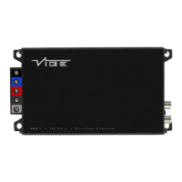
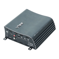
Explains the Power/Protect LED status and the required fuse type and rating for the amplifier.

Power and Speaker Terminals

Describes the connection points for power supply and speaker cables.

Set Up Section

Gain Control Adjustment Routine

Step-by-step guide for setting amplifier gain to match the source unit volume and prevent distortion.

Crossover Setting Guidance

Advice on selecting crossover modes (FULL/HPF) based on speaker size for optimal performance and longevity.

Specification

Overview

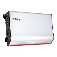
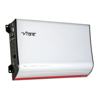
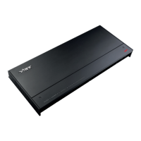
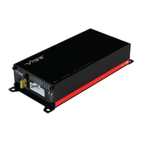
The VIBE POWERBOX 65.4M-V7 is a compact, 4-channel Class D amplifier designed and engineered in England, part of the Powerbox Micro series. It is intended to enhance the audio system in a vehicle, providing amplified sound for speakers. The amplifier is designed for ease of installation and offers several features for sound customization and protection.

Function Description:

The POWERBOX 65.4M-V7 serves as an aftermarket audio amplifier, taking an audio signal from a head unit and amplifying it to power up to four speakers. It features both high-level (speaker level) and low-level (RCA) inputs, making it versatile for integration with various head units. The amplifier incorporates an "Autosense" auto turn-on circuit for high-level inputs, eliminating the need for a separate remote turn-on wire in such configurations. For low-level RCA inputs, a remote turn-on wire from the head unit is still required. The device includes adjustable gain controls for both front and rear channels, allowing users to match the amplifier's input sensitivity to the head unit's output. Crossover mode select switches (FULL/HPF) are available for both front and rear channels, enabling users to filter out low frequencies to protect smaller speakers and optimize sound quality. The amplifier is equipped with power and protection LEDs to indicate operational status and potential issues.

Important Technical Specifications:

  • Model: POWERBOX65.4M-V7
  • Configuration: 4 channel
  • Dimensions (H x W x D): 1.5" x 7.4" x 3.2" (37mm x 187mm x 82mm)
  • RMS @ 4Ω Stereo: 4 x 65 watts
  • RMS @ 2Ω Stereo: N/A
  • RMS @ 4Ω Mono: N/A
  • Maximum Power: 520 watts
  • Recommended Fuse: 20 Amps (ATC fuse)
  • Frequency Response: 20Hz - 20kHz
  • Crossover Type: HP / Full
  • Crossover Range: 80Hz (fixed for HPF)
  • Topology: Class D

Usage Features:

  • Mounting Guidelines: The amplifier should be mounted in a dry location on a solid surface. It is crucial not to mount the amplifier upside down, as this can lead to overheating and damage. Sufficient airflow (at least two inches) around the casing is recommended for effective cooling.
  • Power Cable: If not using the vehicle's ISO cable, a minimum of 12 gauge cable is recommended for the power connection. The power cable should be connected directly to the battery, with rubber grommets used when passing through bulkheads to prevent damage. A fuse/circuit breaker of at least the same value as the amplifier's fuse (20A) must be placed inline with the power cable, no more than 18 inches from the battery. The fuse should only be fitted after the entire installation is complete.
  • Ground Cable: If not using the vehicle's ISO cable, a minimum of 12 gauge cable is recommended for the ground connection. The ground cable should be connected directly to the vehicle's chassis, to bare metal, and its length should be kept to an absolute minimum. Connecting the ground cable to seatbelt anchor points is not recommended.
  • RCA Cables: Depending on the head unit and the number of speakers, one, two, or three RCA cables may be needed. These cables should be routed carefully, away from potential interference sources like wiring harnesses. It is recommended to run RCA cables on opposite sides of the car from power cables to minimize interference.
  • Auto Turn On (High Level Input Only): The Autosense circuit allows the amplifier to turn on and off automatically when using high-level inputs, without a remote turn-on wire. For low-level (RCA) inputs, a remote turn-on wire from the head unit is still necessary.
  • Gain Control: Separate gain controls for front and rear channels allow users to match the amplifier's input signal to the head unit's output. The setup routine involves setting the amplifier gain to minimum, ensuring head unit bass boost is 0 dB, setting head unit crossovers to flat, and bass/treble to zero. The head unit volume should be turned to approximately 3/4, then the amplifier gain slowly increased until distortion is heard or an uncomfortable listening level is reached, at which point the gain should be slightly reduced.
  • Crossover Mode Select: Switches allow selection between FULL range output or High Pass Filter (HPF) at 80Hz. This helps protect smaller speakers from low frequencies and optimize overall sound quality.
  • Power / Speaker Terminals: These terminals are used for connecting DC power and speaker input/output cables.
  • RCA Output: When using high-level input, the RCA leads provide an output that can be used to connect an additional amplifier or audio device.

Maintenance Features:

  • Fuse Replacement: The amplifier uses a 20A ATC fuse. Only replace it with a fuse of the same value.
  • Heatsink: During normal operation, the heatsink may become very hot. Users should avoid touching it during or immediately after use. When installing, ensure the heatsink does not come into contact with materials that could be damaged by heat, such as upholstery or plastics.
  • Warranty: All VIBE products come with a 12-month warranty from the date of original receipt and proof of purchase. The online warranty card should be completed within seven days. The original receipt and packaging should be retained. The warranty covers manufacturing defects but excludes damage from improper installation, moisture, excessive heat, chemical cleaners, UV radiation, negligence, misuse, accident, abuse, amplifier clipping/distortion, unauthorized repairs, or use of sealant. Products returned without a returns authorization number are also not covered.
  • Technical Support: UK customers can call 09067031420 for technical enquiries (calls cost 50p per minute, correct as of 01/02/12, available Mon-Fri 9:00am-5:30pm GMT). International customers should contact their local VIBE distribution agent or visit www.vibeaudio.co.uk/contact for more details.

Vibe Power Box Micro POWERBOX 65.4M Specifications

General IconGeneral
BrandVibe
ModelPower Box Micro POWERBOX 65.4M
CategoryAmplifier
LanguageEnglish

Related product manuals