Do you have a question about the Vibe SLICK a1 and is the answer not in the manual?
Guidance on selecting and installing appropriate power and ground cables.
Requirements for connecting the ground cable to the vehicle chassis.
How to connect the remote turn-on lead from the source unit.
Best practices for routing RCA cables to avoid interference.
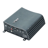
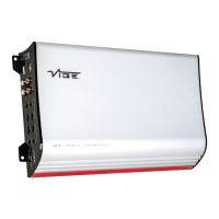
Diagram illustrating connection points for the SLICK a0 model.
Details on input/output RCA, high-level, and speaker terminal connections.
Explanation of gain, crossover, and bass boost controls, plus remote input.
Information on the indicator LED, power connections, and fuses.
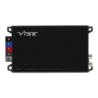
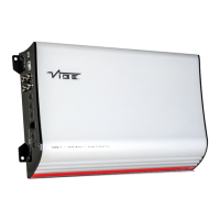
Diagram illustrating connection points for the SLICK a1 model.
Details on RCA and high-level input/output connections for SLICK a1.
Explanation of gain, crossover, and bass boost controls for SLICK a1.
Information on SLICK a1 indicator LED, power connections, and fuses.
Wiring diagram for a stereo setup using two channels.
Wiring diagram for a bridged setup using two channels for higher power.
Wiring diagram for a four-channel stereo setup.
Wiring diagram for a three-channel setup.
Steps to diagnose and resolve power-related issues and protection LED illumination.
Guidance on overheating, blown fuses, and distorted sound.
Information on VIBE's CriticalLink™ range of audio cables and interconnects.
Details on specific amplifier wiring kits for Bass, Stereo, and Active systems.
Information on power capacitors and distribution blocks for audio systems.
| Type | Monoblock Amplifier |
|---|---|
| S/N Ratio | >90dB |
| Crossover Range | 50Hz - 250Hz |
| Bass Boost | 0 - 12dB |
| Subsonic Filter | 10Hz - 50Hz |
| Input Sensitivity | 0.2V - 6V |
| Crossover Type | LPF |