calibrator . In order to produce correct
simulated output
,
the exciting current
should range from 0.5mA to 2mA.
Note
Note
Note
Note
R
R
R
R
esistance
esistance
esistance
esistance
simulation:
simulation:
simulation:
simulation:
A
4-wire system is designed for the
resistance output during the calibration.
If the user adopts a two-wire system,
he should take into consideration the
error (ca.0.1 Ω ) arising from the lead
resistance of the test leads. If the
capacitance between
the resistance
output terminal of the calibrator and the
tested instrument is more than 0.1 μ f,
the calibrator will produce improper
resistance.
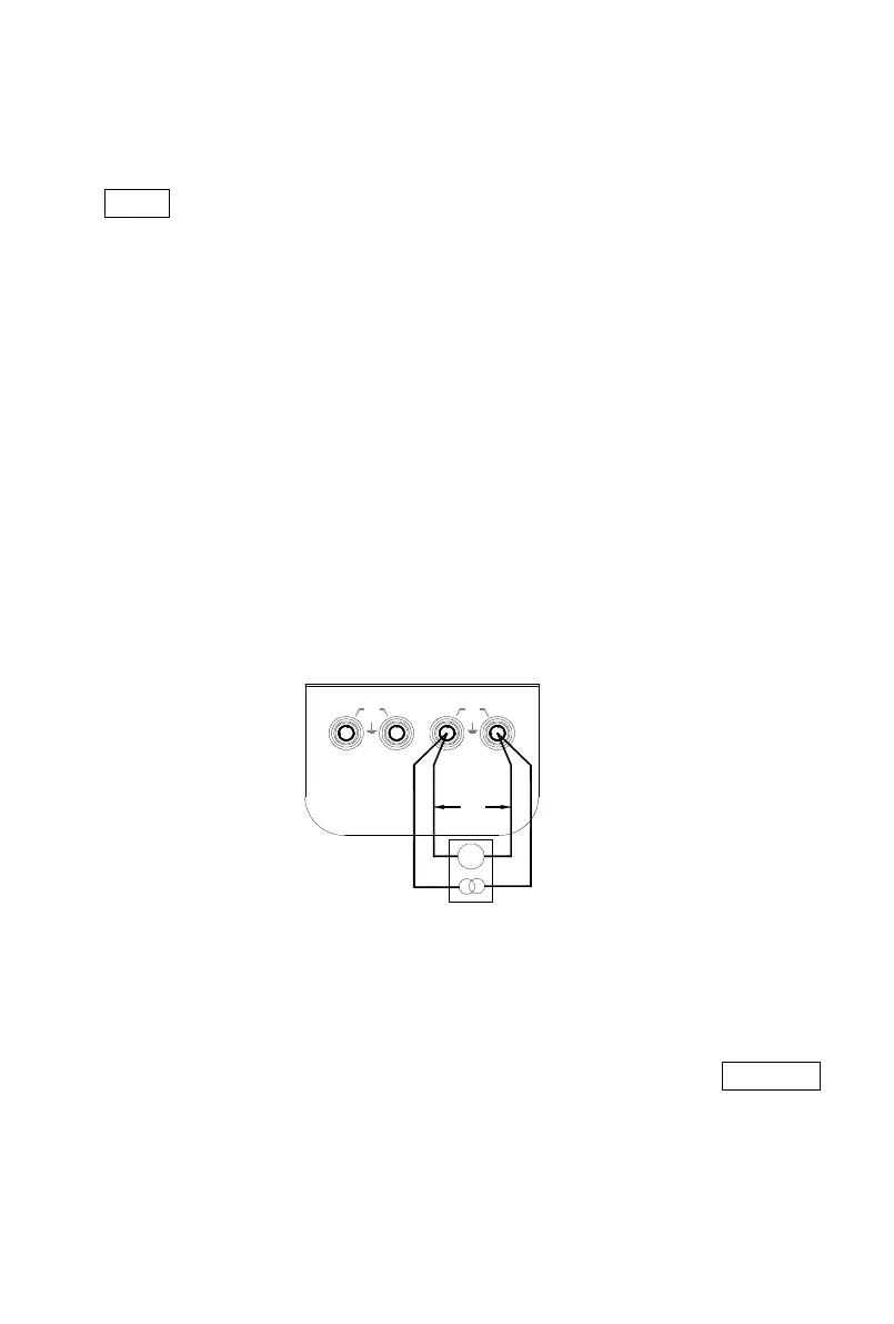
1) Insert one end of the test lead into the output jack of the calibrator
and connect the other end with the input of the user ’ s instrument
as shown in the following diagram: (the dedicated test leads
supplied with the calibrator can be made into a 3-wire
or
4-wire
system for output according to user ’ s requirement.)
2) Press the key 〔 INPUT/OUTPUT
INPUT/OUTPUT
INPUT/OUTPUT
INPUT/OUTPUT
〕 when the symbol ‘ OUTPUT
’
appears in the display. It denotes that the calibrator is in an output
state.
3) P ress the key 〔 FUN
FUN
FUN
FUN
〕 to select the function of resistance
or
RTD
when the corresponding unit ‘ W
’
or
‘ ℃
’
and ‘ Pt100
’
appears in the
4W
Vx
3W
Ix
V
Hi
HiLo
Lo
30V
MAX
30V
MAX
INPUT
OUTPUT