Overload Protection: 0.2A/250V; 10A/250V fuse.
2.4 Resistance
Overload Protection: 250V DC/AC peak value
Note: At range 200Ω, first short-circuit the meter pens to measure the wire resistance. Then subtract it from the real
measurement.
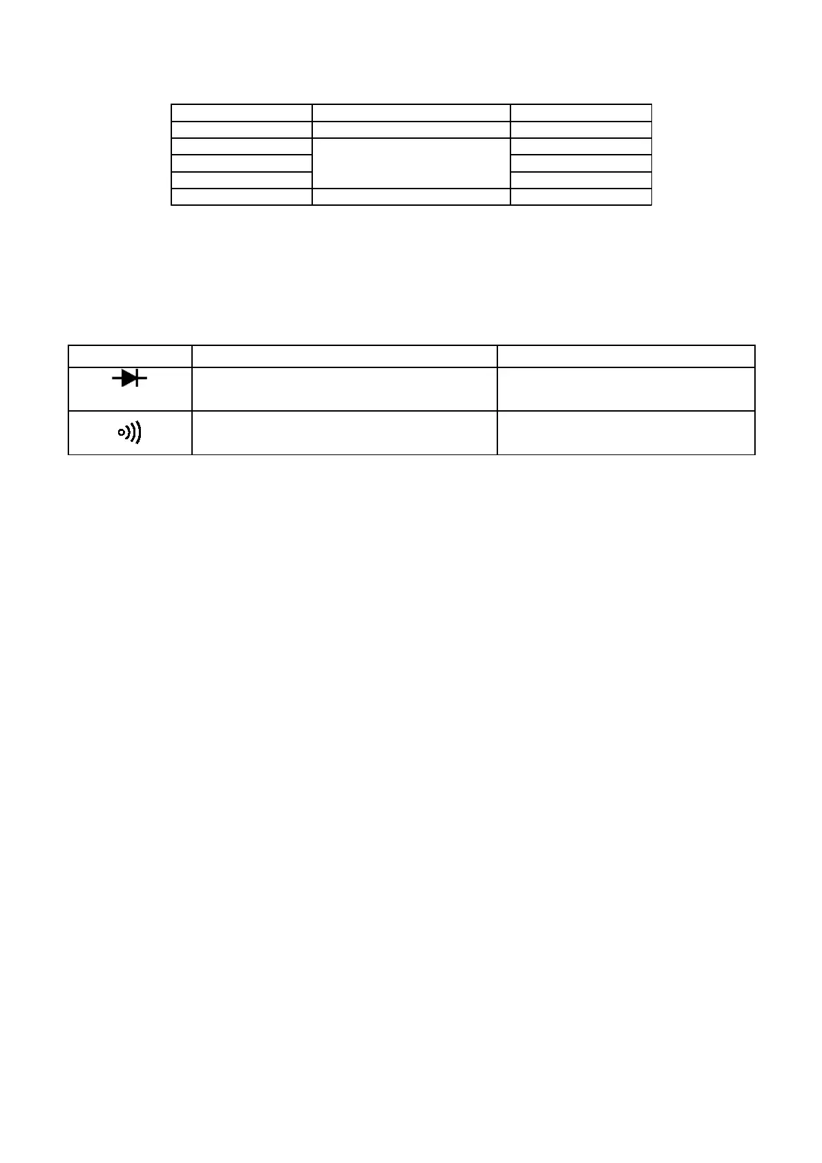
2.5 Diode and continuity test
Range Display Testing Condition
Forward voltage drop of diode Forward DCA is approx. 1mA
,
Backward voltage is apporx.3V
Buzzer makes a long sound while resistance is
less than (70±20)Ω
Open voltage is approx.3V
Overload Protection: 250V DC/AC peak value
2.6 DC Voltage Measurement
1. Apply the black test lead to "COM" terminal and the red test lead to “V/Ω” terminal.
2. Set the knob to a proper DCV range, and connect the test leads crossly to the electric circuit under test. LCD displays polarity
and voltage under test connected by the red test lead.
Note:
1. Firstly, the knob should be set to the highest range if users have no idea about the range of voltage under test. Then select the
proper range based on display value.
2. If MSD displays “1", it means the meter is over range. Please set the knob to a higher range.
3. Do not attempt to input voltage over 600V. Otherwise, it may damage the circuit of the meter.
4. Avoid touching high voltage circuit when measuring it.
2.7 AC Voltage Measurement
1. Apply the black test lead to "COM" terminal and the red test lead to “V/Ω” terminal.
2. Set the knob to a proper ACV range, and connect the test leads crossly to the electric circuit under test.
Note:
1. Firstly, the knob should be set to the highest range if users have no idea about the range of voltage under test. Then select the
proper range based on display value.
2. If MSD displays “1", it means the meter is over range. Please set the knob to a higher range.
3. Do not attempt to input voltage over 600Vrms. Otherwise, it may damage the circuit of the meter.
4. Avoid touching high voltage circuit when measuring it.
2.8 DC Current Measurement
1. Apply the black test lead to "COM" terminal and the red test lead to “V/Ω” terminal (max. 200mA), or put the red test lead to
"10A" terminal (max. 10A).
2. Set the knob to a proper DCA range, and connect the test leads in series to the electric circuit under test. LCD displays
polarity and current value under test connected by the red test lead.
Note:
1. Firstly, the knob should be set to the highest range if users have no idea about the range of voltage under test. Then select the
proper range based on display value.
2. If MSD displays “1", it means the meter is over range. Please set the knob to a higher range.
3. The max input current is 200mA or 10A (depends on the insert position of the red meter pen). Excessive current will melt the