EasyManua.ls Logo

Victor VC9801A User Manual

Victor VC9801A
4 pages
To Next Page IconTo Next Page
Page #1 background imageLoading...
Page #1 background image
DIGITAL MULTIMETER
OPERATION MANUAL
1. GENERAL
The instrument is a stable and high performance digital multimeter driven by
battery. It uses the LCD with 42mm high make the reading is clearly. And the
function of 20sec. back light and overload protection make operation is
convenient.
The instrument has the function of measuring DCV, ACV, DCA, ACA,
resistance, capacitance, and diode, triode and continuity test. The instrument
takes dual-integral A/D converter as key point, is an excellent tools.
2. SAFETY NOTES
This series meter meets the standard of IEC1010. Read it before operation.
1
Do not input the limited voltage of 1000V DC or 750V AC RMS when
measuring voltage.
2
Voltage less than 36V is safety voltage. When measuring voltage higher than
36V DC, 25V AC, check the connection, insulation of test leads to avoid
electric shock.
3
When changing function and range, test leads should be removed from
testing point.
4
Select correct function and range.
5
When measuring current, do not input current over 20A.
6
Safety symbols
exists high voltage
GND
dual insulation
must refer to manual
,“
low battery
3. SPECIFICATION
1
GENERAL
1-1
Displaying : LCD displaying
1-2
Max. indication: 1999
3 1/2
, auto polarity indication
1-3
Measuring method: dual slope A/D transfer
1-4
Sampling rate: approx. 3 times/sec
1-5
Over range indication: MSD displays “1” or“-1”
1-6
Low battery indication: “ ” symbol displays
1-7
Operation: 0
40
relative humidity <80%
1-8
Power
one 9V battery (NEDA1604/6F22 or equivalent)
1-9
Meas.:190×93.5×37 mm
1-10
Weight: approx. 426g
including battery
1-11. Accessories: test leads, instruction manual, holster, gift box and battery
1-12. Test accessories: alligator, triode test accessory
2
TECHNICAL DATA
2-1
Accuracy: ±
RDG% + the lowest digit
at (23±5) ,<75%RH one year
guarantee from production date
2-2
TECHNICAL DATA
2-2-1.DCV
RANGE ACCURACY RESOLUTION
200mV ±(0.5%+3) 100uV
2V 1mV
20V 10mV
200V 100mV
1000V ±(0.8%+10) 1V
Input resistance
all ranges: 10MΩ
Overload protection: 200mV range: 250V DC or AC peak value, other range:
1000V DC or AC peak value
2-2-2.ACV
RANGE
ACCURACY
RESOLU7TION
2V ±(0.8%+5) 1mV
20V 10mV
200V 100mV
750V ±(1.2%+10) 1V
Input resistance: 10MΩ Max
Overload protection: 1000V DC or AC peak value
Frequency response: lower than 200V range: 40~400Hz
750V range:
40~200Hz
Displaying: RMS of sine wave( mean value response)
2-2-3. DCA
RANGE ACCURACY RESOL.UTION
20uA ±(0.8%+10) 0.01uA
200uA 0.1uA
2mA 1uA
20mA 10uA
200mA ±(1.2%+8) 100uA
2A ±(1.5%+5) 1mA
20A ±(2.0%+5) 10mA
Max. measuring voltage drop: 200mV
Max. input current: 20A
within 10 sec.
Overload protection: 2A / 250V fast melt fuse, 20A infused
2-2-4. ACA
RANGE ACCURACY RESOLUTION
20mA ±(1.0%+5) 10uA
200mA ±(2.0%+5) 100uA
2A ±(3.0%+5) 1mA
20A ±(3.0%+10) 10mA
Max. measuring voltage drop:200mV
Max. input current: 20A
less than 10sec.
Overload protection: 2A / 250V fast melt fused, 20A range infused
Frequency response: 40~200Hz
Displaying: rms of sine wave(mean value response
2-2-5. RESISTANCE
Ω
RANGE ACCURACY RESOLUTION
200Ω ±(0.8%+5) 0.1Ω
2kΩ ±(0.8%+3)
Question and Answer IconNeed help?

Do you have a question about the Victor VC9801A and is the answer not in the manual?

Victor VC9801A Specifications

General IconGeneral
BrandVictor
ModelVC9801A
CategoryMultimeter
LanguageEnglish

Summary

General Introduction

1. General

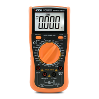
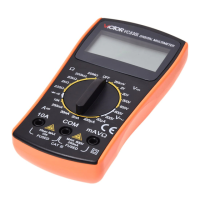
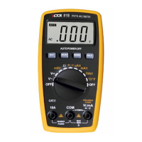
Overview of the digital multimeter, its LCD display, backlight, and overload protection features.

Safety Precautions

6. Safety Symbols

Explanation and identification of important safety symbols used in the manual.

Specifications Overview

1. General Specifications

Details on display, maximum indication, measurement method, sampling rate, and operating conditions.

Technical Data

2-1. Accuracy

General accuracy statement and conditions for the instrument's measurements.

2-2-1. DCV Measurement Data

Technical specifications for DC Voltage (DCV) measurement, including ranges, accuracy, and protection.

2-2-2. ACV Measurement Data

Technical specifications for AC Voltage (ACV) measurement, including ranges, accuracy, and frequency response.

2-2-3. DCA Measurement Data

Technical specifications for DC Current (DCA) measurement, including ranges, accuracy, and overload protection.

2-2-4. ACA Measurement Data

Technical specifications for AC Current (ACA) measurement, including ranges, accuracy, and frequency response.

2-2-5. Resistance Measurement Data

Technical specifications for Resistance (Ω) measurement, including ranges, accuracy, and resolution.

2-2-6. Capacitance Measurement Data

Technical specifications for Capacitance measurement, including ranges, accuracy, and overload protection.

2-2-7. Diode and Continuity Test Data

Specifications for Diode and Continuity testing, including display values and test conditions.

2-2-8. Transistor hFE Data Test

Specifications for Transistor hFE (gain) testing, including range and testing conditions.

2-2-9. Live Wire Identifying Data

Specifications for Live Wire identifying function, including range, alarm, and test condition.

Operation Guide

4-1. Panel Description

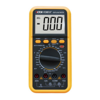
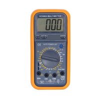
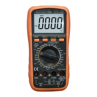
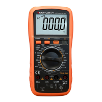
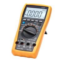
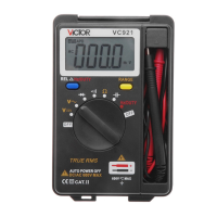
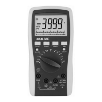
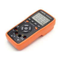
Identification and function of each control and display element on the multimeter's panel.

4-2. DCV Measurement

Step-by-step instructions for performing DC Voltage measurements.

4-3. ACV Measurement

Step-by-step instructions for performing AC Voltage measurements.

4-4. DCA Measurement

Step-by-step instructions for performing DC Current measurements.

4-5. ACA Measurement

Step-by-step instructions for performing AC Current measurements.

4-6. Resistance Measurement

Instructions for measuring resistance, including notes on accuracy and safety.

4-7. Capacitance Measurement

Instructions for measuring capacitance, including polarity and handling precautions.

4-8. Transistor hFE

Procedure for testing transistor gain (hFE) using the multimeter.

4-9. Diode and Continuity Test

Instructions for performing diode forward voltage drop and continuity tests.

4-10. Data Hold

How to use the Data Hold function to freeze the displayed measurement.

4-11. Auto Power Off

Information on the automatic power-off feature and how to restart the meter.

4-12. Backlight Indication

How to activate the backlight and notes on its usage and effect on battery life.

4-13. Live Wire Verify

Procedure for testing for live AC voltage using the multimeter.

Maintenance and Troubleshooting

5. Maintenance

Guidelines for maintaining the multimeter, including cleaning and storage.

Troubleshooting Guide

Common issues like no display, no current input, or big errors and their solutions.

Related product manuals