Do you have a question about the Victor VC890D and is the answer not in the manual?
Key safety precautions to avoid electric shock, damage, and ensure proper operation.
Details on display, measuring method, sampling rate, and environmental conditions.
Specifies ranges, accuracy, resolution, and overload protection for DC voltage.
Specifies ranges, accuracy, resolution, and frequency response for AC voltage.
Specifies ranges, accuracy, resolution, and overload protection for DC current.
Specifies ranges, accuracy, resolution, and frequency response for AC current.
Details ranges, accuracy, resolution, and open voltage for resistance measurements.
Specifies ranges, accuracy, resolution, and overload protection for capacitance.
Details test conditions, display values, and overload protection for diode/continuity.
Provides range, display, and test conditions for hFE transistor testing.
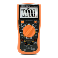
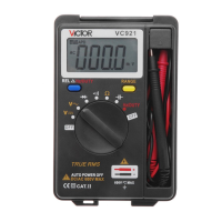
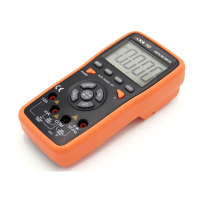
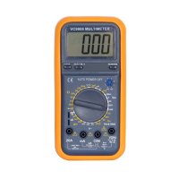
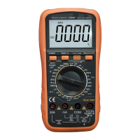
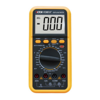
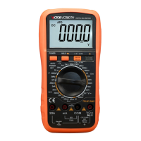
Identifies and explains the function of each control and display element on the meter's front.
Step-by-step instructions for measuring DC voltage accurately and safely.
Step-by-step instructions for measuring AC voltage accurately and safely.
Procedure for measuring DC current, including range selection and safety notes.
Instructions for measuring AC current, with emphasis on current limits and fuse protection.
How to perform resistance measurements, including notes on high resistance stabilization.
Steps for measuring capacitance, including polarity and discharge precautions.
Guide for testing diodes and continuity, including buzzer activation criteria.
Instructions for testing transistor gain (hFE), including NPN/PNP identification.
Details the automatic power-off feature and how to restart the meter.
Advice on meter handling, storage, and cleaning to ensure longevity.
Procedure for replacing the battery when the low battery indicator appears.
Guidance on replacing fuses, emphasizing the use of specified types.
Troubleshooting steps for common issues like no display or measurement errors.
| Brand | Victor |
|---|---|
| Model | VC890D |
| Category | Multimeter |
| Language | English |