3
1
/
2
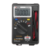
DIGITAL MULTIMETER OPERATION MANUAL
1. INTRODUCTION
This instrument is a high performance stability, battery operated, 3½ digital, 25mm high
character jumbo LCD reading to 1999 multi-meter with the function of measuring DC and
AC voltage, DC and AC current, Resistance, temperature and Capacitance, Diode and
Continuity test, data hold. The Dual-slop A/D converter uses CMOS technology for
auto-zero, polarity selection and over-range indication. Full overload protection is provided.
Because of its outstanding features, it is most suitable for use in production line, lab, R & D,
maintenance and repair work.
2. SAFETY NOTE
The meter meets the standards of IEC1010. Read the operation manual carefully before operation.
2-1.Do not input limit over-ranged.
2-2.The voltage below 36V is safety. To avoid electric shock, check whether the test leads
are connected correctly, whether the insulation is good when measuring over 36DCV
or 25ACV.
2-3.Remove the test leads when changing function and range.
2-4.To select correct function and range, beware of error operation.;
2-5.Do not operate the meter if battery case and back cover is not fixed.
2-6.Do not input voltage when measuring resistance.
2-7.Remove test leads from test point and turn off the power before replacing battery and fuse.
2-8.Safety symbols.
“ ”Exists dangerous voltage,“ ” GND,“ ”Dual insulation
“ ”The operator must refer to the manual,“ ”Low battery
3. CHARACTERISTIC
3.1 GENERAL
3-1-1. Display: LCD displaying.
3-1-2. Max. displaying: 1999(3 1/2digit)auto polarity indication.
3-1-3. Measuring method : dual slope A/D conversion.
3-1-4. Sampling rate: approx. 3 times/second.
3-1-5. Over range indication: the MSD displays“1” or“-1”.
3-1-6. Low battery indication:“ ” appears.
3-1-7. Operation environment: Temperature (0℃ to 40℃), humidity<85%RH.
3-1-8. Storage environment: Temperature (-10℃ to 50℃), humidity<85%RH.
3-1-9. Power:9V×1(NEDA1604/6F22 or equivalent model).
3-1-10. Size: 155mm×90mm×48mm
3-1-11. Weight: approx. 270g(including battery).
3-1-12. Accessories: manual, holster, gift box, test lead a pair of TP01 thermocouple s、
9Vbattery.
3.2 ELECTRICAL SPECIFICATIONS
3-2-1. Accuracy is ±(percentage of reading + number of digit) at 23±5℃,<75%RH.
3-3-2.DCV
Input impedance: 10MΩ of all ranges.
Overload protection: 250V DC or AC peak value at 200mV range.
1000V DC or AC peak value at other ranges.
3-2-3.ACV
Input impedance: 10MΩ of all ranges.
Overload protection: 1000V DC or AC peak value.
Frequency response: ≤200V range: (40~400)Hz.
750V range: (40~200)Hz.
Display: Sine wave RMS (mean value response)
3-2-4.DCA
Max input voltage: 200mV
Max input current: 10A (up to 10 seconds)
Overload protection:Fast 0.2A/250V fuse, 10A/250V fuse.
3-2-5.ACA
Max measuring voltage: 200mV
Max input current: 10A (up to 10 seconds)
Overload protection:Fast 0.2A/250V fuse, 10A/250V fuse
Frequency response: (40~200)Hz
Display: Sine wave RMS (mean value response)
3-2-6.RESISTANCE
Open circuit voltage: less than 3V.
Overload protection: 250V DC or AC peak value.
NOTE: at 200Ω range, the test leads should be short-circuit, and measure the down-lead
resistance, then, subtract from the real measuring.
WARNING: Do not input any voltage at resistance range for safety!
3-2-7.CAPACITANCE
Overload protection: 36V DC or AC peak value.
3-2-8. TEMPERATURE
< 400℃±(0.8%+4)
≥ 400℃±(1.5%+15)
Sensor: K-type thermocouple ( banana shape plug )
3-2-9.DIODE AND CONTINUITY TEST
Forward voltage drop
of diode
Forward DC Current approx.
1mA. Reversed DC voltage
approx. 3V.
Buzzer sounds if
resistance
between terminals
V/Ωand COM is less
than about( 30±10)Ω.
Open circuit voltage approx. is
3V
Overload Protection: 250V DC/AC RMS
WARNING: Do not input any voltage at resistance range for safety!
4. OPERATION
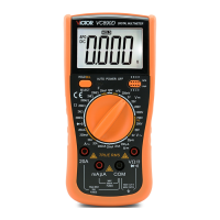
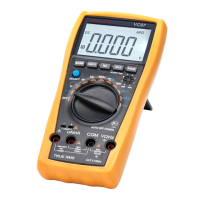
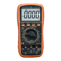
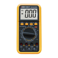
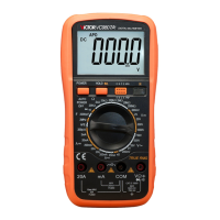
4-1. FRONT PANEL DESCRIPTION
1. LCD display: display measuring data and symbol.
2. DATA HOLD switch: press this key, “H” will
display and the present value will be hold on LCD.
3. FUNCTION and RANGE switch: select the
function and range.
4. test jack of current <200mA,capacitance”+” and
temperature”-“ pole.
5. test jack of 10A current and capacitance “-“.
6. voltage and resistance test jack.
7. GND and temperature “+” test jack.
8. battery case.
4-2. DC VOLTAGE MEASUREMENT
4-2- 1. Insert the black test lead to “COM” jack, the red one to V/Ω jack.
4-2-2. Set the range knob to a proper DCV range, connect the test leads across to the circuit
under tested, the polarity and voltage of the point which red lead connect will display
on LCD.
NOTE:
1. If the measured voltage is unsure beforehand, should set the range knob to the highest
range, then, switch to a proper range according to the displayed value.
2. If LCD displays “1”, it means over range, should set the range knob to a higher range.
4-3.AC VOLTAGE MEASUREMENT
4-3-1.Insert the black test lead to “COM” jack, the red one to V/Ω jack.
4-3-2. Set the range knob to a proper ACV range, connect the test leads across to the circuit
under tested.
NOTE: