DIGITAL
DIGITAL
DIGITAL
DIGITAL
MULTIMETER
MULTIMETER
MULTIMETER
MULTIMETER
OPERATION
OPERATION
OPERATION
OPERATION
MANUAL
MANUAL
MANUAL
MANUAL
1.
1.
1.
1.
GENERAL
GENERAL
GENERAL
GENERAL
The meter is a stable 4 1/2 multimeter with LCD display, driven by battery. It's widely
used on measuring DCV,
ACV,
DC current, AC current, resistance, conductance,
capacitance, diode, transistor, continuity test and frequency, and has the function of
overload pro tection, auto power off and data hold, etc.
2.
2.
2.
2.
SAFETY
SAFETY
SAFETY
SAFETY
Meet with IEC1010 standard
Read the safety note before operation.
2-1 . Do not input a limited value over-ranged.
2-2
.
The voltage below 36V is safety.
To
avoid electric shock, check whether the test lead s
are connected correctly, whether the insulation is good when measuring over 36 V DCV or
25
V
ACV.
2-3 . The test leads should be removed from the testing point when changing function and
range.
2-4 . Choose correct function and range to avoid wrong operation.
2-5 . Do not take measurement if the battery is not fit on or rear cover ked.
2-6. Do not input voltage when measuring resistance.
2-7. Remove the test leads and turn the power off before replacing battery or fuse.
2- 8 . Specification of safety signal
“ ” existing dangerous volt “ ” GND “ ” dual insulation
“ ” operator must refer to the manual “ ” low battery indication
3.
3.
3.
3.
SPECIFICATION
SPECIFICATION
SPECIFICATION
SPECIFICATION
3-1
3-1
3-1
3-1
. GENERAL
GENERAL
GENERAL
GENERAL
3-1-1 .Displaying: LCD display
3-1-2 . Max. displaying : 19999 ( 4 1/2 ) auto-polarity display
3-1-3 . Measuring method : dual-slope A/D transfer
3-1-4 . Sa mpling rate : approx. 2- 3 times/sec
3-1-5. Max. common mode voltage: 500V DC/AC RMS
3-1-6 . Over-range display : the MSD displays “ 1 ” or “ - 1 ”
3-1-7 . Low battery display
:
“ ” displays
3-1-8 . Operation : (0 ~ 40) ℃ , relative humidity <80% R.H
3-1-9. Storage: (-10 ~ 50) ℃
,
relative humidity <80% R.H
3-1-10. power: 9V battery (NEDA1604/6F22 or equivalent)
3-1-11. Dimension: 19 2 mm × 95 mm × 48 mm
3-1-12. Weight: approx. 455 g (including battery)
3-2
3-2
3-2
3-2
. TECHNICAL
TECHNICAL
TECHNICAL
TECHNICAL
SPECIFICATION
SPECIFICATION
SPECIFICATION
SPECIFICATION
3-2-1 . Accuracy : ± ( a% × reading + digit ) TEM : ( 23 ± 5 ) ℃ , <75% R.H , one year
3-2-2 . TECHNICAL
DATA
3-2-2- 1 .DCV
Input impedance : 1 0M Ω for all ranges
Over - range protection : 250 V DCV or AC peak factor at 2 00mV range,
1000 V DCV or AC peak factor at other range
3-2-2-2.ACV
Input resistance: 2 M Ω for all ranges
Overload protection: Range 200mV: DC 250V or AC peak value.
Other ranges: DC 1000V or AC peak value
Frequency response : below 200V : (40~400)H z , 750V range: (40~200)H z
Displaying : 1): sine wave RMS ( mean value response )
2): Some can
’
t turn to “ 0 ” which is normal phenomenon; it can
’
t affect the
test accuracy
3-2-2-3.DCA
Max. measuring volt drop: 200 mV
Max. input current: 2 0A ( less than 10 seconds )
Overload protection: 0.2A / 250V self resume fuse ; 20A range without fuse.
3-2-2-4.ACA
Max. measuring volt drop : 200 m V
Max. input current : 2 0A ( less than 1 0 seconds )
Overload protection : 0.2A / 250V self resume fuse , 2 0A range without fuse.
Frequency response : 40H z ~200Hz
Displaying : sine wave RMS ( mean value response )
3-2-2- 5 . RESISTANCE ( Ω )
Open voltage : less than 3 V
Overload protection : 250V DCV or ACV peak factor
Note
Note
Note
Note
:
In 200 Ω range
,
should make the test leads short, and measure the resistance of th e
wire, then, subtracts from the actual measuring value.
± 【 5 % (reading-10.00) + 30 】
3-2-2-6.CAPACITANCE
Testing frequency: 400Hz
Overload protection : 36V DCV or
AC
V peak factor ;630mA/250V fuse protection
3-2-2-7.FREQUENCY
Input sensitivity : 120 m V RMS
Overload protection : 250V DC or AC peak factor (less than 10sec.)
Note: 200kHz maybe can
’
t return to “ 0 ” ,this phenomenon is normal, it can
’
t affect
the test accuracy.
3-2-2-8.DIODE AND CONTINUITY TEST
Overload protection : 250V DC or AC peak factor
Warning: do not input any voltage value at this range for safety!
3-2-2-9. hFE
3-2-2-10. Conductance ( resistance range: 10 , 000M Ω -10M Ω )
Open voltage is approx:3V
4.operation
4.operation
4.operation
4.operation
4-1
4-1
4-1
4-1
. Fr
Fr
Fr
Fr
o
o
o
o
nt
nt
nt
nt
panel
panel
panel
panel
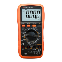
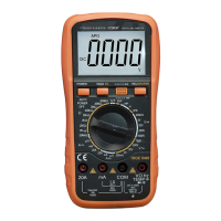
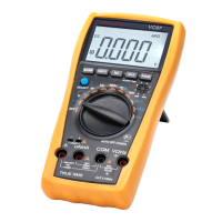
1 . LCD : display the measured value
2 -1 Power switch : turn on or off the power
2-2. Backlight key: turn on or off the power
2-3. hFE testing terminal : for measuring
transistor hFE
2-4. HOLD key : press the key down, the
measured value will be hold and “ H ”
signal appears; press it down again, “ H ”
signal disappears and out of the HOLD mode.
2-5. Continuity buzzer key
3 . Knob switch: for changing function and range
4. Testing terminal for 20A current
5. Testing terminal for less than 200 mA current and conductance
Buzzer rings, the impedance
between the two testing points is
less than (70 ± 20) Ω
Base DC current is approx.
10u A , Vce is approx. 3V