Do you have a question about the Victor 6056B and is the answer not in the manual?
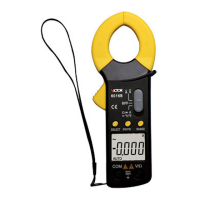
Introduction to the digital clamp meter and a critical safety warning.
Lists the components included with the digital clamp multimeter.
Explains warning symbols, danger marks, and compliance with safety standards.
Advises caution against electric shock and proper probe usage for voltage measurements.
Instructions for correct battery replacement and prohibiting unauthorized circuit modifications.
Precautions during measurement, storage environment, and handling high voltages.
Ensuring correct switch settings and safety during calibration or repair.
Prohibits switch conversion during measurement and explains low battery indication.
Defines standard electrical symbols for safe and effective operation.
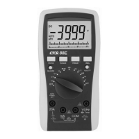
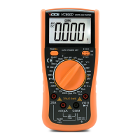
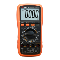
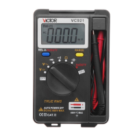
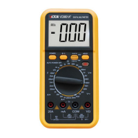
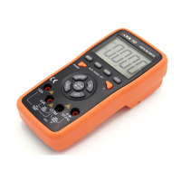
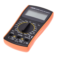
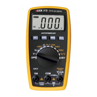
Identifies and describes the external parts and ports of the clamp multimeter.
Explains the meaning of various icons and indicators shown on the multimeter's LCD.
Details the specific functions of the SELECT, HOLD, and REL keys.
Explains the auto power-off feature, its activation, and cancellation.
Describes buzzer feedback and a table showing key effectiveness across measurement modes.
Visual guide on which keys are active and effective for different measurement functions.
Details display mode, max display, measurement mode, and conversion rate.
Covers over-range, low battery, auto power-off, and environmental operating conditions.
Defines accuracy, ambient conditions for accuracy, and calibration warranty period.
Instructions for setting the function/range switch for DC Voltage measurement.
Explains connection, reading results, and provides technical indicators for DCV.
Instructions for setting the function/range switch for AC Voltage measurement.
Provides ACV technical indicators, frequency response, and important notes.
Instructions for setting the function/range switch for Resistance measurement.
Details connection steps and provides crucial notes for resistance measurements.
Lists technical indicators for resistance and critical safety precautions.
Instructions for setting the function/range switch for Diode measurement.
Important notes for diode measurement, including display indications for faults.
Instructions for setting the function/range switch for Continuity Test.
Details the continuity test procedure and provides technical indicators for diode/continuity.
Instructions for setting the function/range switch for Capacitance measurement.
Details the capacitance measurement procedure and provides technical indicators.
Instructions for setting the function/range switch for Frequency measurement.
Details the frequency measurement procedure and provides technical indicators.
Instructions for setting the function/range switch for AC/DC Current measurement.
Details the procedure for AC/DC current measurement, including clamp usage.
Provides technical indicators for DC and AC current measurements.
Guidelines for routine cleaning and general care of the multimeter.
Safety warning regarding test bar removal before opening the bottom cover.
Guidance on storage, battery removal, and usage restrictions on different gears.
Steps for preparing to replace the battery, including switching off the meter.
Detailed instructions for safely installing or replacing the battery.
Information regarding manual changes and user liability for incorrect operations.
| Diode Test | Yes |
|---|---|
| Continuity Buzzer | Yes |
| Data Hold | Yes |
| Power Supply | 9V battery |
| Display | 3.5 digit LCD |
| DC Current | 20mA/200mA/10A |
| AC Current | 200mA/10A |
| Resistance | 200Ω/2kΩ/20kΩ/200kΩ/2MΩ/20MΩ |
| Capacitance | 20nF/200nF/2µF/20µF/200µF |
| Frequency | 20kHz |
| DC Voltage | 200mV/2V/20V/200V/1000V |