Do you have a question about the Victor VC830L and is the answer not in the manual?
Summary of device's main specifications and capabilities, including display and battery.
Details accuracy, operating conditions, and warranty information for measurements.
Specifications for Direct Current Voltage (DCV) measurement ranges and accuracy.
Specifications for Alternating Current Voltage (ACV) measurement ranges and accuracy.
Specifications for Direct Current Amperage (DCA) measurement ranges and accuracy.
Specifications for Resistance measurement ranges and accuracy.
Details for testing diodes and continuity, including display and conditions.
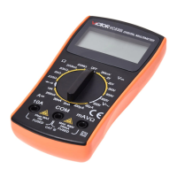
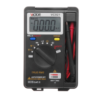
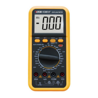
This document outlines the operation and maintenance of a pocket-sized digital multimeter, a versatile tool designed for various electrical measurements in laboratory, household, and enthusiast settings.
The multimeter is primarily used to measure direct current voltage (DCV), alternating current voltage (ACV), and direct current amperage (DCA). Beyond these core functions, it also offers capabilities for resistance measurement, diode testing, and continuity checks. Its compact design makes it convenient for portable use.
To ensure safe and accurate operation, several key usage features and precautions are highlighted. When measuring, it is crucial to avoid inputting values that exceed the specified range of the device. For voltage measurements, particularly those above 36V DCV or 25V ACV, users must verify the connection and insulation of the test leads to prevent electric shock. It is also advised to keep the test leads clear of the testing point when switching between functions or ranges. A critical safety note for resistance measurement is to never apply voltage to the input terminal.
The device features a clear 22mm digit height LCD display, capable of showing up to 1999 counts, with automatic polarity indication. It has a sampling rate of approximately 3 times per second, ensuring timely readings. An "1" displayed on the MSD indicates an over-range condition, while a specific symbol signals a low battery, prompting replacement. The multimeter operates optimally within a temperature range of 0 to 40 degrees Celsius and a relative humidity of less than 80%. It is powered by a 9V battery.
For DC voltage measurement, the black test lead connects to the "COM" terminal and the red test lead to the "V/Ω" terminal. Users should set the knob to an appropriate DCV range and connect the test leads across the circuit. The LCD will then display the voltage and its polarity. A general guideline is to start with the highest range if the voltage is unknown, then adjust downwards as needed. If the display shows "1," it means the range is too low, and a higher range should be selected. It is imperative not to input voltage exceeding 600V to prevent damage.
AC voltage measurement follows a similar procedure: black lead to "COM," red lead to "V/Ω." The knob should be set to an appropriate ACV range, and the test leads connected across the circuit. As with DCV, starting with the highest range for unknown voltages is recommended, and voltages over 600Vrms should be avoided.
For DC current measurement, the black test lead connects to "COM." The red test lead can be connected to either the "V/Ω" terminal for currents up to 200mA or the "10A" terminal for currents up to 10A. The knob is set to the appropriate DCA range, and the test leads are connected in series with the circuit. The display will show the current value and its polarity. Again, starting with the highest range is advised, and exceeding the maximum input current (200mA or 10A, depending on the red lead's position) will likely blow the fuse.
Resistance measurement involves connecting the black test lead to "COM" and the red test lead to "V/Ω." The knob is set to the desired resistance range, and the leads are connected across the resistance under test. If the LCD displays "1," the resistance is over the selected range, requiring a higher range selection. For resistances above 1MΩ, the reading may take a few seconds to stabilize, which is normal. An open circuit input terminal will display an overload. When measuring in-line resistors, it is crucial to ensure the power is off and all capacitors are fully discharged. Applying voltage to the resistance range is strictly forbidden, despite the meter having some voltage protection in this range.
Diode testing involves connecting the black test lead to "COM" and the red lead to "V/Ω" (red being positive). The knob is set to the diode symbol, and the test leads are connected to the diode. The red lead connects to the positive polarity of the diode, and the display shows the approximate forward voltage drop.
Continuity testing is performed by setting the knob to the continuity symbol. Applying the test leads to two points in a circuit will cause an internal buzzer to sound if the resistance between those points is less than (70±20)Ω.
The multimeter is a precise instrument and should not be modified. Several maintenance notes are provided to ensure its longevity and accurate performance. It is crucial not to input voltage exceeding DC600V or AC 600Vrms. Voltage measurements should never be attempted on the resistance range. The meter should not be used if the battery is incorrectly placed or if the back case is not properly screwed. Before replacing the battery or fuse, always remove the test leads from the testing points and turn off the meter.
Battery replacement is indicated by a specific symbol on the LCD. To replace the battery, unscrew the battery cover, remove the old 9V battery, insert a new one, and then reinstall and screw the cover back on.
Fuse replacement should only be performed when the device is powered off. The process involves unscrewing the battery cover, removing the battery, opening the back cover, and replacing the fuse with one of the same specification.
The manual also states that its content is considered correct, but users who find errors or missing parts should contact the manufacturer. The company disclaims liability for accidents or hazards resulting from user mal-operations. The functions described are not intended for special purposes. Users are warned against modifying the circuit, especially when dealing with high voltage measurements, and assume responsibility for any consequences of such modifications.
| Type | Digital Multimeter |
|---|---|
| DC Current Range | 200μA/2mA/20mA/200mA/10A |
| AC Current Range | 200μA/2mA/20mA/200mA/10A |
| Resistance Range | 200Ω/2kΩ/20kΩ/200kΩ/2MΩ/20MΩ |
| Diode Test | Yes |
| Continuity Buzzer | Yes |
| Data Hold | Yes |
| Battery | 9V (6F22) |
| Operating Temperature | 0°C to 40°C |
| Display | LCD |
| DC Voltage Range | 200mV/2V/20V/200V/600V |
| AC Voltage Range | 200V/600V |
| Capacitance Range | 2nF/20nF/200nF/2μF/20μF |
| Frequency Range | 2kHz/20kHz |
| DC Voltage Accuracy | ±(0.5%+2) |
| DC Current Accuracy | ±(1.0%+2) |