2-3-10. Diode and continuity testing
RANGE Reading Test Condition
Forward voltage drop of diode
Forward DCA is approx.
1mA. backward voltage is
approx. 3V
Buzzer makes a long sound while
resistance is less than (70±20)Ω
Open voltage is approx. 3V
Overload protection: DC 250V or AC peak value.
CAUTION: DO NOT INPUT VOLTAGE AT THIS RANGE!
2-3-11. Transistor hFE DATA TEST
Range Displaying range Testing condition
hFE NPN or PNP
0~1000
Base current is approx. 10uA.
Vce is approx. 3V
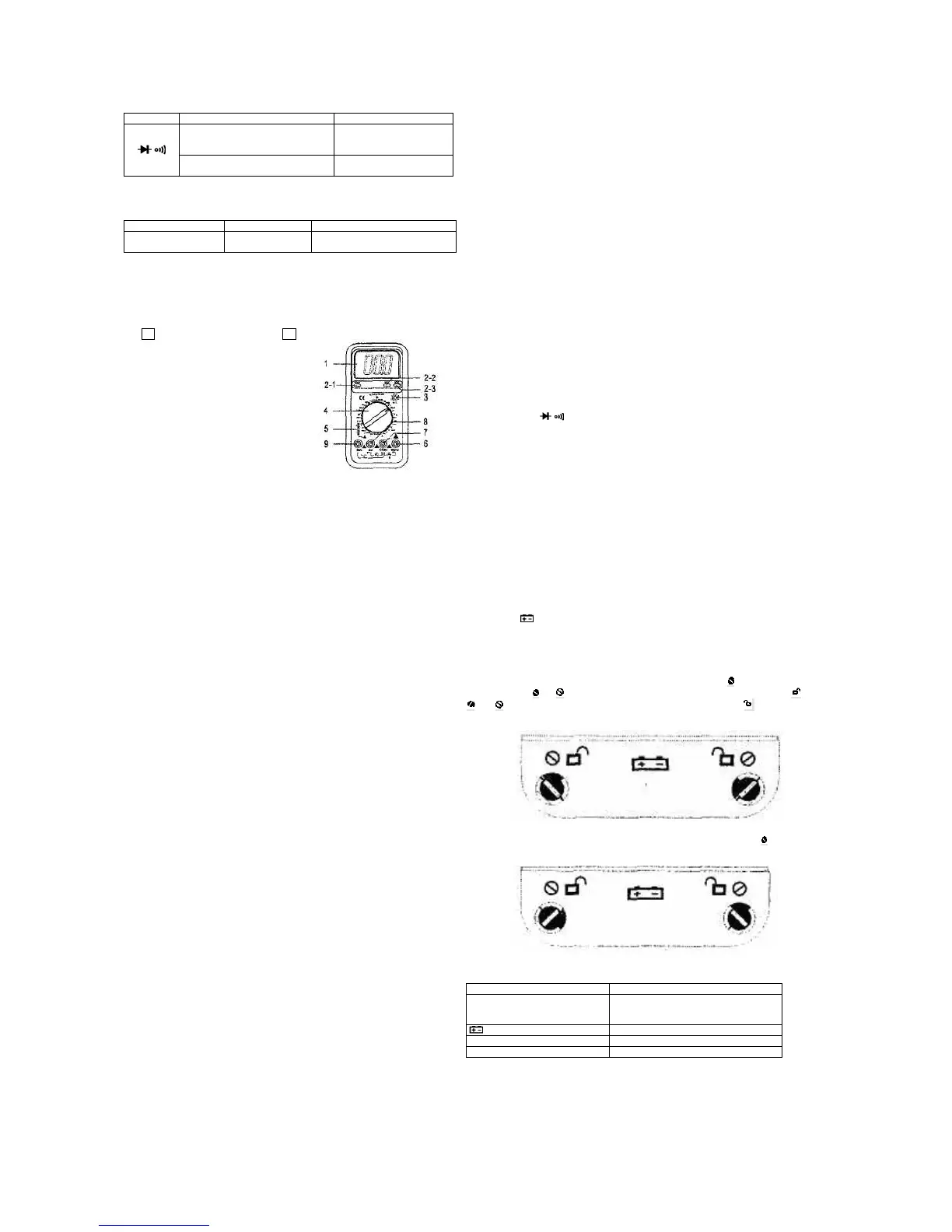
4. OPERATION
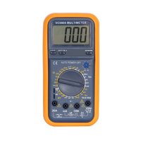
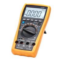
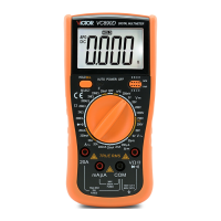
4-1. Panel description
1. LCD: display the measuring value and unit.
2-1. POWER switch: turn on/off the power.
2-2. PK HOLD key: press it, the max. of presently measured value is held on LCD
and PH symbol displays. Press it again, PH symbol disappears, and the meter is
exited the holding mode.
2-3. DC/AC key: set DC or AC working mode,
2-4. B/L key: turn on/off backlight.
3. hFE hole: to measure hFE of triode.
4. Range knob: to select measuring function
and range.
5. Capacity (Cx) or inductance (Lx) COM.
6. Voltage, resistance and frequency COM.
7. GND.
8. COM for measuring current less than
200mA.
9. COM for measuring current 20A.
SEE THE FIG.
4-2. Voltage measurement
1. Apply the black test lead to “COM” terminal and the red one to V/Ω/Hz terminal.
2. Setup the Knob on a proper range “V”. If the voltage range is unsure beforehand,
please set it on the max., then measure diminishingly to reach a resolute value.
3. Press the DC/AC key down to AC mode to measure AC voltage. Oppositely,
resile the key to DC mode to measure DC voltage.
4. Connecting the test leads reliably with the tested circuit, the voltage value will be
displayed on LCD. While testing a DC voltage, the reading is voltage and polarity of
the point connected by the red lead.
NOTE:
1. While the reading is 1 or OL, the voltage is beyond the present range. Now you
need to set the knob to the higher.
2. Do not input a voltage over DC 1000V or AC 700V. Please keep the test leads off
the circuit while switching the function or range.
3. Be carefully while measuring a high voltage. DO NOT touch the circuit.
4-3. Current measurement
1. Apply the black test lead to “COM” terminal and the red one to “mA” or “20A”
terminal.
2. Set the knob to a proper range A. If the current under tested is unsure
beforehand, please set it on the max., then measure diminishingly to reach a
resolute value.
3. Press the DC/AC key down to AC mode to measure AC current. Oppositely,
resiling the key to DC mode to measure DC current.
4. Connecting the leads to the tested circuit in series, the current value is displayed
on LCD. While testing a DC current, the reading is the value of current and polarity
of the point connected by the red lead.
NOTE:
1. If the LCD displays 1 or OL, it means the current is over range. Now you need to
set the knob to the higher.
2. Max. input current is 200mA or 20A (subject to where the red test lead apply to),
too large current will blow the fuse. Be sure the test is less than 10 seconds. Please
keep the leads off the circuit while switching the function and range knob.
4-4. RESISTANCE MEASUREMENT
1. Apply the black test lead to COM terminal and the red one to V/Ω/Hz terminal.
2. Set the knob to a proper resistance range, and connect the leads crossly with the
resistor under tested.
NOTE:
1. The LCD displays 1 or OL while the resistance is over the selected range. The
knob should be adjusted to a higher range.
2. When input terminal is in open circuit, overload displays.
3. When measuring in line resistor, be sure that the power is off and all capacitors
are released completely,
4. Do not input any volt at resistance range.
5. When measuring value is over 1MΩ, the reading will take a few seconds to be
stable. It’s normal for high resistance measuring.
4-5. CAPACITANCE MEASUREMENT
1. Apply the knob to proper capacitance range, and insert the capacitor under
tested into “Cx” terminal.
2. Connect test leads with the two points of capacitor, be wary of polarity if
necessary.
NOTE:
1. If the capacitance under tested is over the max. value of selected range, LCD
displays 1 or OL, thus, should set the knob to a higher range.
2. It’s normal that there is a remained value on LCD before capacitance
measurement, and it doesn’t affect the measurement.
3. When measuring at large capacitance range, if capacitor is crept badly or broken,
LCD displays a value and it’s unstable.
4. Release the capacitor completely before measuring.
4-6. INDUCTANCE MEASUREMENT
Set the knob to a proper inductance range and insert the inductor to LX terminal.
NOTE:
1. The LCD displays 1 or OL while the tested inductance is over the selected range.
Thus, the knob should be set to a higher range.
2. The inductance may be different due to different resistance on a same inductor.
3. At 2mH range, should make the test leads short and measure the inductance of
wire, then, subtract from real measurement.
4-7. TEMPERATURE MEASUREMENT
Set the knob to °C range, insert the black plug of cold end of thermocouple into mA com and
the red plug to V/Ω/Hz com, put working end into measurement place. Display reading is the
temperature of measurement place in °C.
NOTE:
1. When input terminal is in open circuit, if the ambient temperature is over 18°C, LCD
displays the ambient temperature, If ambient temperature is lower than 18°C, LCD displays
an un-normal temperature.
2. Do not try to change the thermocouple, or, the accuracy cannot be guaranteed.
3. Do not input any volt at a temperature range.
4-8. FREQUENCY MEASUREMENT
1. Apply test leads or shield cable to COM and V/Ω/Hz terminal.
2. Set the knob to frequency range, connect test leads or cable crossly to signal source or
tested load.
NOTE:
1. When input over 10V RMS, reading is workable but accuracy is not guaranteed.
2. It is better to use shield cable to measure small signal at noisy environment.
3. Be careful when measuring high volt circuit.
4. Do not input voltage over DC 250V or AC peak value.
5. Auto range is from 2kHz to 10MHz.
4-9. TRANSISTOR hFE
1. Set the knob to hFE range.
2. Verify the transistor under tested is NPN or PNP, insert emitter, base and collector to
proper jack.
4-10. DIODE AND CONTINUITY TEST
1. Apply the black test lead to “COM” terminal and the red one to V/Ω/Hz terminal the polarity
of red lead is “+”).
2. Set the knob to range, connect test leads with the diode under tested, the red test
connect to diode positive polarity, the reading is the approx. value of diode forward volt drop.
3. Apply test leads to two points of tested circuit, if the inner buzzer sounds, the resistance is
less than (70±20)Ω.
4-11. PEAK VALUE HOLD
Press down the key, the max. of presently measured value is held on LCD. Press up the key
and the function is cancelled.
4-12. AUTO POWER OFF
The meter will be into sleeping mode when it works for (20±10) minutes. Press “POWER”
key twice to restart the power.
5. MAINTENANCE
Do not try to modify the electric circuit.
5-1. Keep the meter away from water, dust and shock.
5-2. Do not store and operate the meter under the condition of high temperature, high
humidity, combustible, explosive and strong magnetic place.
5-3. Wipe the case with a damp cloth and detergent, do not use abrasives and alcohol.
5-4. If do not operate for a long time, should take out the battery to avoid leakage.
5-4-1. When “ ” signal displays, should replace the battery following the steps.
5-4-1-1. Unlock the button and remove the battery case, (see fig.1).
5-4-1-2. Take out the old battery and replace the new one. It’s better to use alkaline battery
for longer life.
5-4-1-3. Fit on the battery case and lock the button (see fig.2).
z How to remove the battery case
Unlock the button according to indication on the case, i.e. switch on both sides counter-
clockwise, when and signal on left side are at the same direction, it’s unlocked ; when
and signal on right side are at the same direction, it’s unlocked . When the signals
are the same as fig.1, the battery case can be removed.
Fig.1
z How to fit on the battery case
Lock the button according to the indication on the case, i.e. switch two on both sides
clockwise, when the signals are the same as fig.2, the battery case is fit on.
Fig.2
5-4-2. FUSE REPLACEMENT: Please use the same size fuse as replacement.
6. If the meter does not work properly, check the meter as following:
Fault Solution
No reading on LCD
turn on the power
set the HOLD key to acorrect mode
Replace battery
Signal appears Replace battery
NO current or temperature input Replace fuse
Big error Value Replace battery
SPE-V9808+-2010X
 Loading...