Do you have a question about the Victron energy 24/3000 and is the answer not in the manual?
| Model | 24/3000 |
|---|---|
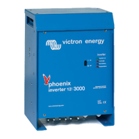
| Type | Pure Sine Wave Inverter |
| Input Voltage | 24V DC |
| Output Voltage | 230V AC |
| Efficiency | 93% |
| Weight | 18 kg |
| Peak Power | 6000W |
| Transfer Time | 20 ms |
| Rated Power | 3000VA / 2400W |
| Output Power | 3000VA |
| DC Input Voltage Range | 19-33V DC |
| Frequency | 50 Hz |
| Protection | Overload, Short Circuit, Over Temperature |
General safety guidelines for product usage and compliance.
Instructions and precautions for safe product installation.
Details about SinusMax technology, efficiency, and performance.
Information on the inverter's high start-up power for difficult loads.
Features for increasing power output via parallel or 3-phase configurations.
Explanation of the automatic transfer switch function within the system.
Details on the inverter's programmable relay, default and other uses.
Methods for configuring inverter settings using various interfaces.
How to operate the inverter using the main on/off switch.
Options available for remotely controlling the inverter's operation.
Explanation of the meaning of various LED status indicators on the inverter.
Guidelines for selecting an appropriate and safe installation location.
Detailed instructions and specifications for connecting DC battery cables.
Procedures and safety notes for connecting the AC output cabling.
Information on various optional connection types and their setup.
Overview of the default factory settings for stand-alone operation.
Detailed explanations of inverter configuration parameters.
Steps and requirements for configuring the inverter via a computer.
Guide to setting configuration parameters using a VE.Net panel.
Instructions for configuring settings using the inverter's DIP switches.
Table detailing common problems, their causes, and troubleshooting solutions.
Explanation of LED indicators specific to VE.Bus system configurations.
Detailed dimensions and mounting information for the 3k inverter cabinet.
Detailed dimensions and mounting information for the 5k inverter cabinet.