Do you have a question about the Victron energy MultiPlus-II 24/3000/70-50 and is the answer not in the manual?
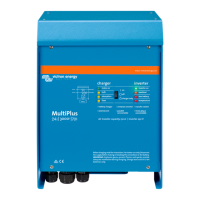
| Model | MultiPlus-II 24/3000/70-50 |
|---|---|
| Output Power (Continuous) | 3000 VA |
| Continuous output power at 25°C | 2400 W |
| Output Voltage | 230 VAC |
| Output Frequency | 50 Hz |
| AC Input Voltage Range | 187-265 VAC |
| AC Input Frequency Range | 45 - 65 Hz |
| Efficiency | 95% |
| Battery Voltage | 24 VDC |
| Charger Output Current | 70 A |
| Transfer switch | Yes |
| Output Power (Surge) | 6000 VA |
| Protection | Overload, short circuit |
| Operating temperature range | -40°C to +65°C |
| Input Voltage Range | 19.0 - 33.0 VDC |
General safety instructions for using the product.
Safety precautions for installing the product.
Safety guidelines for transporting and storing the product.
Explanation of symbols used on the product enclosure for safety.
Describes standalone applications in boats and vehicles.
Discusses combined on-grid and off-grid PV systems.
Details the battery charging capabilities of the MultiPlus-II.
Details charging for lead-acid batteries.
Mentions compatibility with Victron Lithium Smart batteries.
Refers to website for other Li-ion battery compatibility.
Provides further information on batteries and charging.
Explains ESS functionality for grid feedback.
Explains the on/off and charger-only switch functions.
Describes methods for remote control of the unit.
Details equalisation and forced absorption charging modes.
Explains the meaning of the LED status indicators.
Outlines the procedure for safely shutting down the unit.
Specifies requirements for the installation location.
Details how to connect the battery cables.
Explains the connection of AC cabling.
Describes various optional connection possibilities.
Details how to connect for remote control.
Explains the programmable relay function.
Describes analog/digital input/output ports.
Explains voltage sense connection for compensation.
Details temperature sensor connection for compensation.
Instructions for connecting multiple units in parallel.
Information on split-phase and three-phase operation.
Lists standard factory settings for immediate use.
Provides explanations for various configuration settings.
Outlines methods for configuring the MultiPlus-II.
Describes the VE.Bus Quick Configure Setup software.
Details the VE.Bus System Configurator software.
Information on using the VEConfigure software.
Explains configuration using the VictronConnect app.
Lists general problems and their causes/solutions.
Explains special LED indications for errors.
Details VE.Bus LED indications for OK codes and errors.
Explains VE.Bus OK codes.
Details VE.Bus error codes and interpretation.