Do you have a question about the Victron energy MultiPlus-II 48/5000/70-50 230V GX and is the answer not in the manual?
Details the physical placement and mounting requirements for the unit.
Provides guidelines for safely storing and transporting the equipment.
Explains the meaning of various safety and compliance symbols on the product.
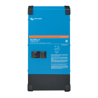
Highlights the key capabilities and functionalities of the MultiPlus-II GX.
Details the battery charging aspects, including adaptive algorithms and battery types.
Explains the adaptive 4-stage charging process for lead-acid batteries.
References additional resources for battery and charging information.
Specifies requirements for using Victron Lithium Smart batteries.
Provides a link for compatibility information on other lithium battery types.
Explains the function of the main on/off and charger-only switch.
Describes methods for controlling the unit remotely.
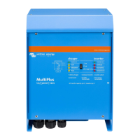
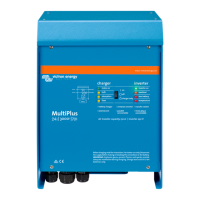
Details the functionality and information displayed by the GX card and LCD screen.
Explains how error codes are displayed and where to find more information.
Outlines the correct steps to safely power down the MultiPlus-II unit.
Details the physical placement and mounting requirements for the unit.
Provides guidance on connecting the DC power supply and battery cables.
Explains the procedures for connecting the AC input and output power.
Describes how to establish an internet connection for remote monitoring via the VRM portal.
Covers various optional connections, including remote control, relays, and sensors.
Details the default factory settings and considerations for initial use.
Explains methods and tools for configuring the unit, including VictronConnect and VE.Bus software.
Provides guidance on firmware updates and checking version information.
Lists common problems, their causes, and solutions for troubleshooting.
Details specific error codes generated by the VE.Bus system and their meanings.
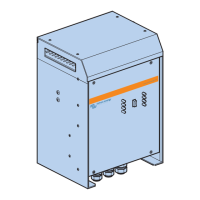
Illustrates the physical layout and function of all connection terminals.
Shows a schematic representation of the unit's internal components and connections.
Explains the multi-stage charging process used by the unit.
Details how battery temperature affects charging voltage settings.
Provides the physical dimensions and weight of the unit.
Details the physical placement and mounting requirements for the unit.
Provides guidelines for safely storing and transporting the equipment.
Explains the meaning of various safety and compliance symbols on the product.
Highlights the key capabilities and functionalities of the MultiPlus-II GX.
Details the battery charging aspects, including adaptive algorithms and battery types.
Explains the adaptive 4-stage charging process for lead-acid batteries.
References additional resources for battery and charging information.
Specifies requirements for using Victron Lithium Smart batteries.
Provides a link for compatibility information on other lithium battery types.
Explains the function of the main on/off and charger-only switch.
Describes methods for controlling the unit remotely.
Details the functionality and information displayed by the GX card and LCD screen.
Explains how error codes are displayed and where to find more information.
Outlines the correct steps to safely power down the MultiPlus-II unit.
Details the physical placement and mounting requirements for the unit.
Provides guidance on connecting the DC power supply and battery cables.
Explains the procedures for connecting the AC input and output power.
Describes how to establish an internet connection for remote monitoring via the VRM portal.
Covers various optional connections, including remote control, relays, and sensors.
Details the default factory settings and considerations for initial use.
Explains methods and tools for configuring the unit, including VictronConnect and VE.Bus software.
Provides guidance on firmware updates and checking version information.
Lists common problems, their causes, and solutions for troubleshooting.
Details specific error codes generated by the VE.Bus system and their meanings.
Illustrates the physical layout and function of all connection terminals.
Shows a schematic representation of the unit's internal components and connections.
Explains the multi-stage charging process used by the unit.
Details how battery temperature affects charging voltage settings.
Provides the physical dimensions and weight of the unit.
| Model | MultiPlus-II 48/5000/70-50 230V GX |
|---|---|
| Output Power (Continuous) | 5000 VA |
| Output Voltage | 230 VAC |
| Output Frequency | 50 Hz |
| Battery Charger | 70 A |
| GX Device | Yes |
| Maximum AC Input Current | 50 A |
| Transfer Time | 20 ms |
| Battery Voltage | 48 VDC |
| Operating Temperature Range | -40 to +65 °C |
| Output Power (Surge) | 10000 VA |