Reference Description Connection
11. Battery voltage sense +
12. Battery voltage sense -
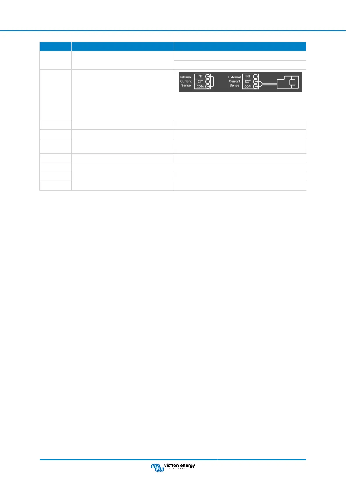
K External current sensor
To connect the current sensor; remove the wire bridge
between the INT and COM terminals, connect the red
sensor wire to the EXT terminal and connect the white
sensor wire to the COM terminal.
L 2x RJ45 VE-BUS connector for remote control and/or parallel / three-phase operation
M Connector for remote switch Short connection to switch “on”.
N Dedicated BMS-Can port (VE.Can not
supported)
O USB port
P Reset Button Reboots the GX card component only
Q Ethernet Port
R VE.Direct Port
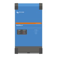
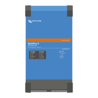
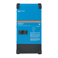
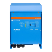
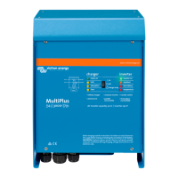
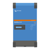
MultiPlus-II inverter/charger off-grid Australia
Page 20 Appendix
 Loading...