EasyManua.ls Logo

Victron energy Phoenix MultiPlus 24/3000/70 User Manual

Victron energy Phoenix MultiPlus 24/3000/70
101 pages
To Next Page IconTo Next Page
Page #1 background imageLoading...
Page #1 background image
MANUAL
Phoenix MultiPlus
Con VE.Bus
12/3000/120
24/3000/70
48/3000/35
Remark:
DIP switch functionality has changed.
Parallel and 3-phase systems can be now configured with DIP
switches.
EN NL F D E Appendix

Table of Contents

Other manuals for Victron energy Phoenix MultiPlus 24/3000/70

Question and Answer IconNeed help?

Do you have a question about the Victron energy Phoenix MultiPlus 24/3000/70 and is the answer not in the manual?

Victron energy Phoenix MultiPlus 24/3000/70 Specifications

General IconGeneral
ModelPhoenix MultiPlus 24/3000/70
Input Voltage24 VDC
Output Power3000 VA
Peak Power6000 VA
Output Voltage230 VAC
Transfer Time20 ms
Battery Charger70 A
AC Input Current16 A
Frequency50 Hz
ProtectionOverload, Short Circuit, Over Temperature
Operating Temperature-40°C to +65°C
Humidity95% (non-condensing)

Summary

1. SAFETY INSTRUCTIONS

Installation

Instructions for proper installation and grounding of the product.

2. DESCRIPTION

PowerControl and PowerAssist

Explanation of PowerControl for shore current and PowerAssist for peak load supplementation.

2.2 Battery Charger

Adaptive 4-Stage Charging

Details the adaptive battery management system and its stages.

3. OPERATION

3.4 LED Indications

4. Installation

4.2 Location

Guidelines for choosing the optimal installation location for the product.

4.3 Installation Requirements and Battery Connection

Battery Cable Connection Procedure

Detailed steps for correctly connecting the battery cables.

4.5 AC Cabling and Optional Connections

AC Cable Connection Procedure

Instructions for connecting the AC input and output cables safely.

4.6 Optional Connections Details

Parallel Connection Setup

Requirements and procedure for connecting multiple units in parallel.

4.6.7 Three-Phase System Configuration

5. Configuration

5.2 Explanation of Settings

Configuration Settings Explained

5.3 Configuration by Computer

5.3.2 VE.Bus System Configurator and Dongle

Software for advanced applications and systems with four or more Multi's.

5.4 Implementing Settings with VE.Net Panel

5.5 Configuration with DIP Switches

Step 1: Initial DIP Switch Settings

First step in DIP switch configuration for AC input limit and AES.

5.5.1.3 Charging Current Limitation

Setting the charging current limitation using DIP switches.

5.5.1.4 System Configuration with DIP Switches

5.5.2 Step 2: Other Settings

ds8-ds7: Setting Charging Voltages

Setting charging voltages using DIP switches ds8 and ds7 for battery compatibility.

Step 2: Exemplary Settings for Parallel and 3-Phase Modes

7 Error Indications

7.1 General Error Indications

General troubleshooting guide for common error indications and their solutions.
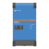
7.2 Special LED Indications

7.3 VE.Bus LED Indications

7.3.2 VE.Bus Error Code Interpretation

8. Technical Specifications

APPENDIX C: Parallel Connection

APPENDIX D: Three Phase Connection

APPENDIX E: Charge Characteristic

Related product manuals