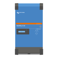
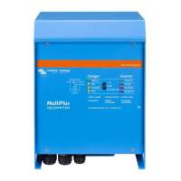
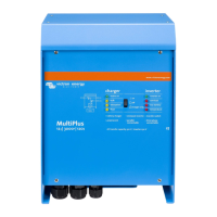
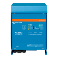
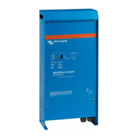
Do you have a question about the Victron energy MultiPlus-II 12|3000|120-50 and is the answer not in the manual?
Details AC input/output voltage, split-phase operation, and inverter mode behavior for the device.
Covers automatic switching, auxiliary output, PowerControl, PowerAssist, and programmable relay functions.
Explains the adaptive battery management system, including charge stages and battery types.
Describes the front panel switch functions for operating the device and its charger.
Explains how to control the MultiPlus-II remotely using a switch or control panel.
Details the procedures for equalisation and forced absorption charging modes.
Explains the meaning of various LED indicators for charger and inverter status.
Guidelines for selecting a suitable dry, well-ventilated installation area and mounting the product.
Instructions for connecting battery cables, including capacity, fuse, and cross-section recommendations.
Details on connecting AC input and output cabling, including grounding and wire gauge.
Describes optional connections like remote control, programmable relay, and sensors.
Presents the default factory settings for single-unit operation and notes on battery compatibility.
Provides brief explanations for various configuration settings like inverter frequency and voltage ranges.
Details the hardware and software required for configuring the MultiPlus-II system.
Lists common problems, their causes, and solutions for identifying and resolving errors.
Explains specific LED patterns that indicate special operating conditions or errors.
Covers VE.Bus OK codes and error codes for multi-unit systems, including interpretation guides.
| Model | MultiPlus-II 12/3000/120-50 |
|---|---|
| Inverter Output Power | 3000 VA |
| DC Input Voltage | 12 V |
| Continuous AC Power | 2400 W |
| Peak Power | 6000 W |
| Maximum AC Input Current | 50 A |
| Battery Charger Current | 50 A |
| Efficiency | 95% |
| Transfer Time | 20 ms |
| Battery Voltage | 12 V |
| Maximum Charging Current | 50 A |
| Input Frequency | 45 – 65 Hz |
| Weight | 18 kg |
| Output Voltage | 230 V |
| Output Frequency | 50 Hz |
| Protection | Overload, Short circuit, Over-temperature |
| Operating Temperature | -40 to +65 °C |
| Humidity | 95% non-condensing |
| Input Voltage Range | 90 - 265 V |
