Appendix A. APPENDIX A: Connection overview
CB G H I
M
NK L
J
ED FA
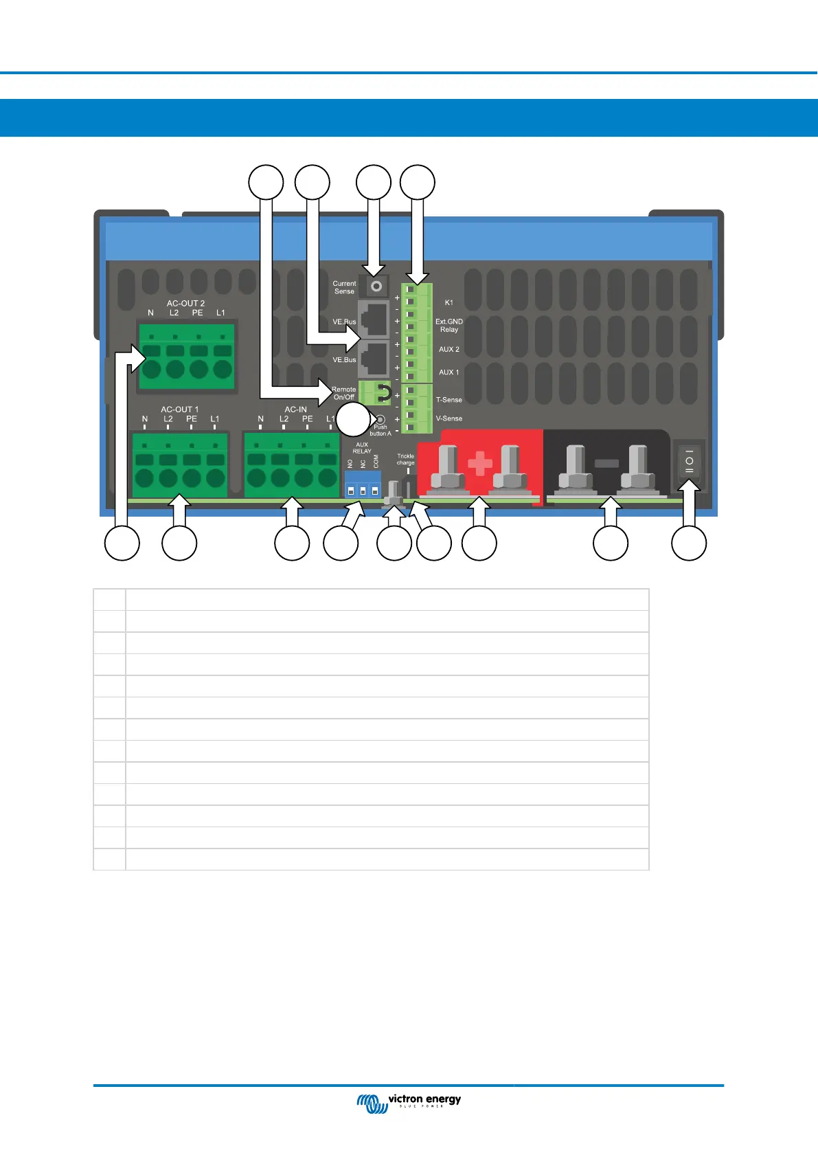
A Load connection AC out2 - From left to right: N (neutral), L2 (phase 2), PE (earth/ground), L1 (phase 1)
B Load connection AC out1 - From left to right: N (neutral), L2 (phase 2), PE (earth/ground), L1 (phase 1)
C AC input - From left to right: N (neutral), L2 (phase 2), PE (earth/ground), L1 (phase 1)
D Auxiliary relay - From left to right: NO, NC, COM
E Primary ground connection (PE) - M8 bolt
F Trickle charge positive terminal (12 and 24V model only)
G Battery positive connections - 2 x M8 bolt
H Battery minus connections - 2 x M8 bolt
I Power switch - To switch: 1=On, 0=Off, ||=charger only
J Push button A - To perform a startup without assistants
K Remote on/off connector - Short contact to switch to “on”
L VE.Bus connectors - 2x RJ45: For remote control and/or parallel / three-phase operation
M External current sensor
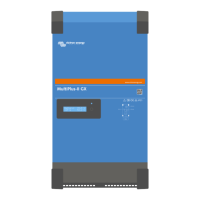
MultiPlus-II 12|3000|120-50 2x120V
Page 26 APPENDIX A: Connection overview
 Loading...