Do you have a question about the Victron energy MultiPlus 12/3000/120 – 50 and is the answer not in the manual?
General safety precautions and product usage guidelines.
Guidelines for safe installation of the product.
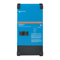
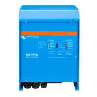
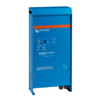
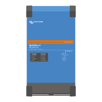
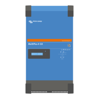
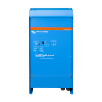
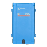
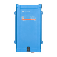
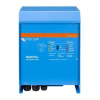
Overview of the MultiPlus, its functions and features.
Explains parallel connection capabilities for increased power.
Feature for managing limited AC input current.
Feature for supplementing power from batteries during peak loads.
Describes the adaptive battery charging process.
Guidance on selecting the appropriate installation location.
Instructions for connecting battery cables correctly.
Guidance on connecting AC input and output cables.
Requirements and procedure for parallel connection.
Steps for setting up three-phase operation.
Procedure for split-phase configuration.
Detailed explanation of various configuration settings.
Setting current limits for PowerControl and PowerAssist.
Initial DIP switch settings for AC input and operation mode.
Procedure for setting remaining parameters via DIP switches.
Setting the AC input current limit using DIP switches.
Setting the battery charge current limit via DIP switches.
Selecting operation modes using DIP switches ds2 and ds1.
Example DIP switch settings for stand-alone operation.
Example DIP switch settings for parallel operation.
Example DIP switch settings for three-phase operation.
Example DIP switch settings for split-phase operation.
Setting absorption, float, and storage voltages via DIP switches.
Troubleshooting common error messages and their causes.
Interpreting VE.Bus error codes displayed by LEDs.
Table for interpreting error codes when Bulk LED is off.
Table for interpreting error codes when Bulk LED flashes.
Table for interpreting error codes when Bulk LED is on.
General explanation of the four stages of charging.
Details of the bulk charging stage.
General safety precautions and product usage guidelines.
Guidelines for safe installation of the product.
Overview of the MultiPlus, its functions and features.
Explains parallel connection capabilities for increased power.
Feature for managing limited AC input current.
Feature for supplementing power from batteries during peak loads.
Describes the adaptive battery charging process.
Guidance on selecting the appropriate installation location.
Instructions for connecting battery cables correctly.
Guidance on connecting AC input and output cables.
Requirements and procedure for parallel connection.
Steps for setting up three-phase operation.
Procedure for split-phase configuration.
Detailed explanation of various configuration settings.
Setting current limits for PowerControl and PowerAssist.
Initial DIP switch settings for AC input and operation mode.
Procedure for setting remaining parameters via DIP switches.
Setting the AC input current limit using DIP switches.
Setting the battery charge current limit via DIP switches.
Selecting operation modes using DIP switches ds2 and ds1.
Example DIP switch settings for stand-alone operation.
Example DIP switch settings for parallel operation.
Example DIP switch settings for three-phase operation.
Example DIP switch settings for split-phase operation.
Setting absorption, float, and storage voltages via DIP switches.
Troubleshooting common error messages and their causes.
Interpreting VE.Bus error codes displayed by LEDs.
Table for interpreting error codes when Bulk LED is off.
Table for interpreting error codes when Bulk LED flashes.
Table for interpreting error codes when Bulk LED is on.
General explanation of the four stages of charging.
Details of the bulk charging stage.
| Brand | Victron energy |
|---|---|
| Model | MultiPlus 12/3000/120 – 50 |
| Category | Inverter |
| Language | English |