31
EN Appendix
Three phase operation (appendix D)
Step 1: Setting ds2 and ds1 for 3-phase operation
As the table above shows, the AC-in current limits for each phase should be set
separately (ds8 thru ds6). Different current limits per phase can be selected.
If a panel is connected, the AC input current limit will equal the value set on the panel
for all phases.
AES can be used on stand alone units only.
The maximum charge current is the same for all devices, and should be set on the
leader only (ds4 and ds3).
Example:
- AC input current limit on the leader and the followers: 25A
- If the charge current on the leader is set to 100% (70A for a MultiPlus 24/3000/70) and the
system consists of three devices, then the effective system charge current is equal to
- 3 x 70 = 210A.
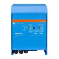
The settings according to this example (9kVA 3-phase system without Multi Control Panel) are as
follows:
Leader (L1) Follower (L2) Follower (L3)
DS-8 AC input 25A off
DS-7 AC input 25A on
DS-6 AC input 25A off
DS-5 AES na
DS-4 Ch. current 3x70A on
DS-3 Ch. current 3x70A on
DS-2 Leader on
DS-1 Leader off
DS-8 AC in 25A off
DS-7 AC in 25A on
DS-6 AC in 25A off
DS-5 na
DS-4 na
DS-3 na
DS-2 Follower 1
off
DS-1 Follower 1
off
DS-8 AC in 25A off
DS-7 AC in 25A on
DS-6 AC in 25A off
DS-5 na
DS-4 na
DS-3 na
DS-2 Follower 2
off
DS-1 Follower 2
on
To store the settings after the required values have been set: press the 'Up' button of the leader
for 2 seconds (upper button to the right of the DIP switches, see appendix A, position J). The
overload and low-battery LED’s will flash to indicate acceptance of the settings.
We recommend making a note of the settings, and filing this information in a safe place.
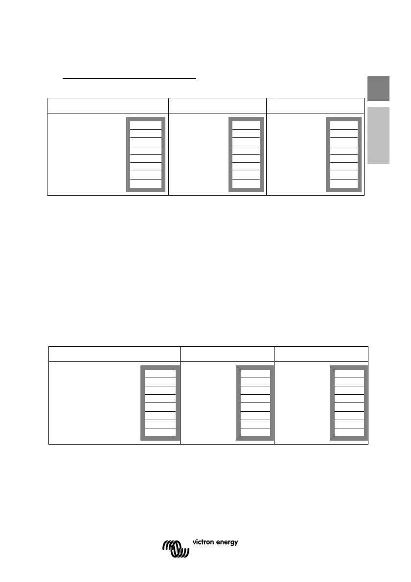
You can now re-use the DIP switches to apply the remaining settings (step 2).
Leader (L1) Follower (L2) Follower (L3)
DS-8 AC input Set
DS-7 AC input Set
DS-6 AC input Set
DS-5 AES na
DS-4 Ch. current Set
DS-3 Ch. current Set
DS-2 Leader on
DS-1 Leader off
DS-8 Set
DS-7 Set
DS-6 Set
DS-5 na
DS-4 na
DS-3 na
DS-2 Follower 1 off
DS-1 Follower 1 off
DS-8 Set
DS-7 Set
DS-6 Set
DS-5 na
DS-4 na
DS-3 na
DS-2 Follower 2 off
DS-1 Follower 2 on
 Loading...