EasyManua.ls Logo

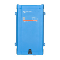
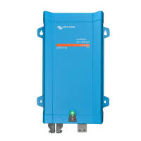
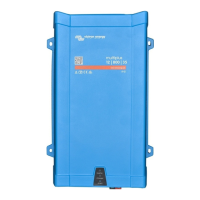
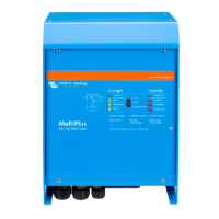
Victron energy MultiPlus 12/1600/70 User Manual

Victron energy MultiPlus 12/1600/70
34 pages
To Next Page IconTo Next Page
Page #1 background imageLoading...
Page #1 background image
Manual
EN
Handleiding
NL
Manuel
FR
Anleitung
DE
Manual
ES
Manuale
IT
Appendix
MultiPlus 1600VA
MultiPlus 12 | 1600 | 70 230V
MultiPlus 24 | 1600 | 40 230V
MultiPlus 48 | 1600 | 20 230V

Questions and Answers:

Victron energy MultiPlus 12/1600/70 Specifications

General IconGeneral
ModelMultiPlus 12/1600/70
Input Voltage12 V
Input Voltage Range9.5 - 17 V
Output Power (Continuous)1600 VA
Continuous AC Output Power at 25°C1300 W
Continuous AC Output Power at 40°C1200 W
Continuous AC Output Power at 65°C1000 W
Output Power (Surge)3000 W
Output Voltage230 VAC
Output Frequency50 Hz or 60 Hz
Efficiencyup to 93%
Battery Charging Current70 A
Weight10.3 kg
Zero Load Power15 W
Zero Load Power in AES mode10 W
AC Input Voltage Range187-265 VAC
AC Input Frequency45 - 65 Hz
Maximum AC input current16 A
Maximum AC output current16 A
Transfer time20 ms

Summary

1. SAFETY INSTRUCTIONS

General Safety and Hazard Warnings

General safety precautions, electric shock hazards, and proper usage guidelines for the equipment.

Transport and Storage

2. PRODUCT DESCRIPTION

Core Functions and Battery Charger System

Details inverter, charger, transfer switch, PowerControl, PowerAssist, and adaptive battery charging.

Solar Energy System Configuration

3. OPERATION MODES

Switching and Remote Control

How to use the main switch and options for remote control of the unit.

LED Status Indicators Explained

4. INSTALLATION GUIDELINES

Location and Cable Connections

Criteria for choosing a location and procedures for connecting battery and AC cables.

DC Fuse and AC Cabling Details

Optional Connection Options

Second Battery, Temperature Sensor, and Remote Control

Connecting a second battery, using the temperature sensor, and remote control methods.

Programmable Relay and Parallel Connection

Details on the programmable relay and requirements for parallel connection.

Three-phase Operation Setup

5. CONFIGURATION SETTINGS

Standard Factory Settings

Overview of default settings suitable for single-unit operation.

Inverter, Input, and Operation Settings

Battery Charging, Grounding, and Power Control

Generator Management and Advanced Settings

Configuration Methods

Computer and DIP Switch Configuration

Steps for configuring settings via VEConfigure software or DIP switches.

DIP Switch Settings Details

Exemplary DIP Switch Configurations

6. PRODUCT MAINTENANCE

7. TROUBLESHOOTING

8. TECHNICAL DATA

Appendix A: Connections Overview

Appendix B: Installation Information

Appendix C: Parallel Connection Diagram

Appendix D: Three-phase Connection Diagram

Appendix E: Charge Algorithm Explained

Appendix F: Temperature Compensation

Appendix G: Physical Dimensions

Related product manuals