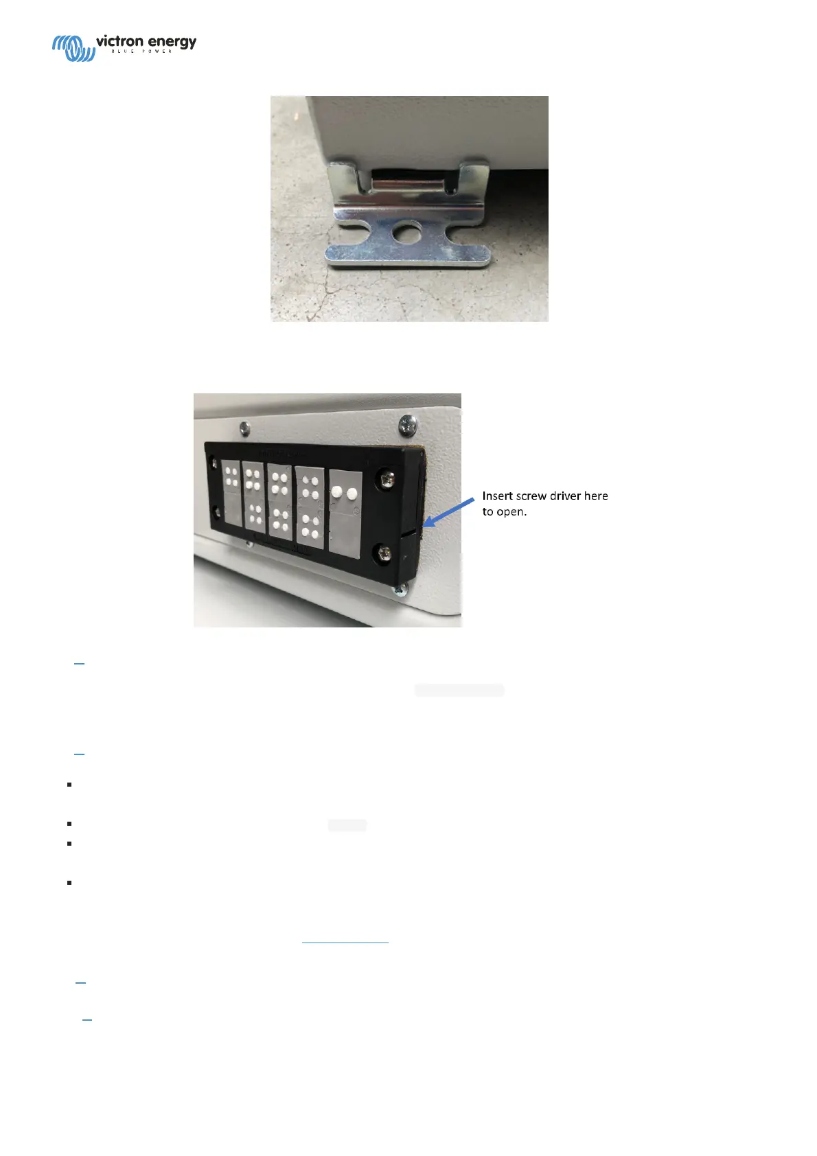
Wire all the cabling through the water tight feed-through at the bottom. Open that feed-through by unlatching the
top with a screw driver. It is not necessary to unscrew it.
2.2. # Power
Connect the battery to -Vin and +Vin on the bottom of the Traco Power power supply. 18 to 78 VDC. Leave the
on/off terminal on the same block open.
2.3. # Communication cables
Connect the VE.Bus to the MK3-USB, on the right. Do not use the single RJ45 socket at the top of the
Controller board. Its non isolated, non functional, and connecting it will lead to a hardware failure.
Connect ethernet to the socket labeled ETH. on the controller board.
The dual RJ45 VE.Can socket on the bottom of the controller board can be used to connect to either a battery
equipped with a Can-BUS BMS. Or to one or more Victron products equipped with a VE.Can port.
Up to 25 VE.Direct devices can be connected to the available VE.Direct ports (1 on the controller board, and 24
divided between the two VE.Direct expanders on the left.
For more connection details, refer to the CCGX Manual.
2.4. # Digital inputs and relays
2.4.1. # I/O module and terminals
On the white enclosure, right next to the MK3-USB, there are four digital inputs and two relays:
 Loading...