Do you have a question about the Victron energy MultiPlus-II GX and is the answer not in the manual?
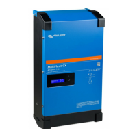
Overview of the Victron MultiPlus-II GX product, its integrated elements, and the manual's scope.
Instructions on how to access the most current version of the manual via a web link and QR code.
Crucial warnings regarding electrical shock, heavy object lifting, and general product usage precautions.
Guidelines for safely transporting and storing the product, including environmental conditions.
Details on proper grounding, wiring standards, environmental conditions, and ventilation for safe installation.
Overview of core features applicable to all system types, such as GX LCD display and connectivity.
Features tailored for hybrid systems combining grid-connected and off-grid solar PV setups.
Detailed explanation of the battery charger functionality, including adaptive charging for various battery types.
Description of Energy Storage Systems (ESS) functionality for feeding energy back into the grid.
Explanation of the three-position switch for controlling product operation modes: Off, On, and Charger Only.
Details on the GX LCD display's on/off behavior, button functions, displayed information, and error codes.
Recommendations for selecting an optimal installation location, considering ventilation and proximity.
Guidance on selecting appropriate battery cables and capacity for optimal product performance.
Step-by-step instructions for correctly connecting the battery cables, including safety warnings.
Instructions for connecting the AC input and output cabling, including safety and protection measures.
Information on various optional connections available for expanded system functionality and control.
Overview of the default factory settings suitable for single-unit operation and initial setup.
Detailed explanations of various configuration settings and their impact on product operation.
Information on using the VEConfigure PC software for product configuration and essential training.
Details on the VE.Bus Quick Configure Setup software for simple system configuration of up to three units.
Information on the VE.Bus System Configurator software for advanced applications and systems with four or more units.
Troubleshooting guide for common problems and error indications with their causes and solutions.
Interpretation of VE.Bus specific error codes displayed on the GX screen, with meaning and solutions.
A visual overview of all connection points on the product and their reference labels.
Schematic block diagram illustrating the internal connections and system architecture.
Diagram and information for connecting multiple units in parallel for increased power.
Diagram and information for configuring the product for three-phase operation.
Graphical representation of the charge current and voltage stages during battery charging.
Graph illustrating how battery charging voltage is adjusted based on temperature.
Technical drawings showing the physical dimensions and mounting details of the product.
| Brand | Victron energy |
|---|---|
| Model | MultiPlus-II GX |
| Category | UPS |
| Language | English |