15. Appendix
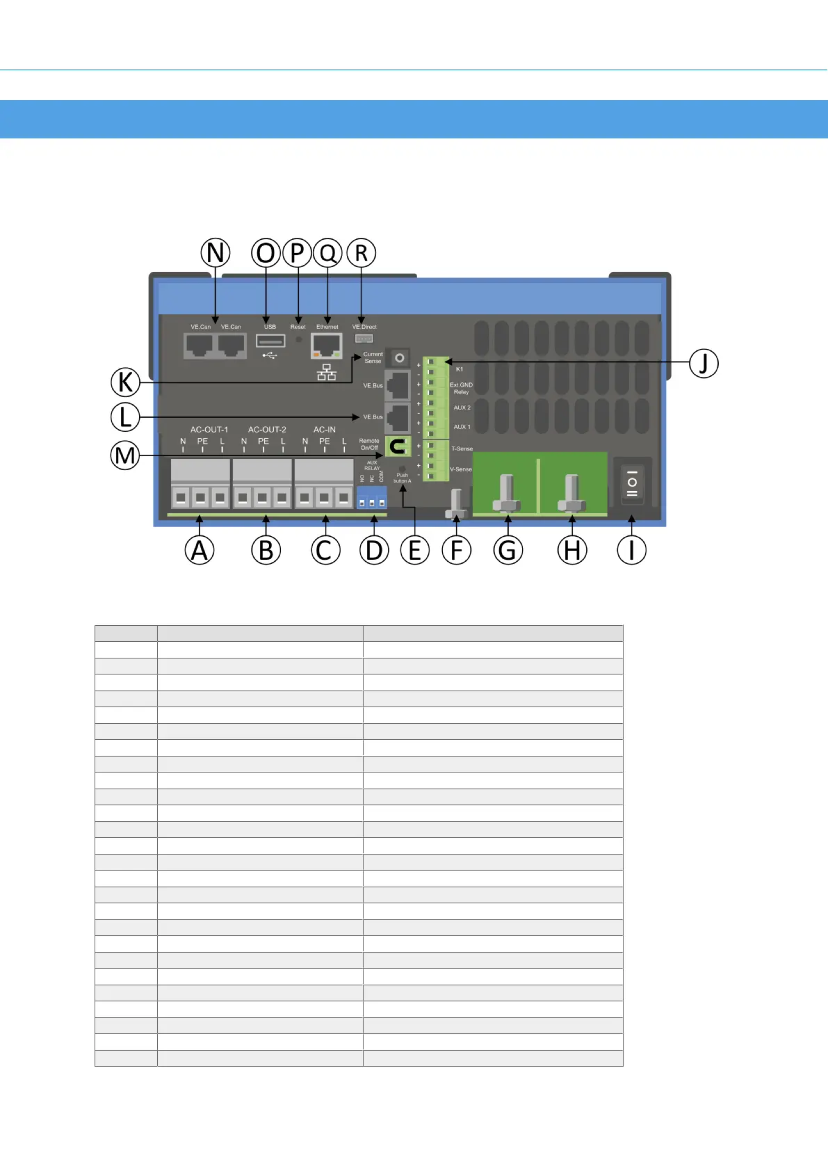
15.1. Appendix A : Connection Overview
Table 1.
Reference Description Connection
A Load connection. AC-OUT-1 Left to right: N (neutral), PE (earth/ground), L (phase)
B Load connection. AC-OUT-2 Left to right: N (neutral), PE (earth/ground), L (phase)
C AC input. AC-IN Left to right: N (neutral), PE (earth/ground), L (phase)
D Programmable (AUX) relay; left to right NO, NC, COM.
E To start without Assistants Press and hold this button when starting
F Primary ground connection M6 (PE)
G battery positive connection. M8
H battery minus connection. M8
I switch -:On, 0:Off, =:charger only
J Terminals top to bottom:
1. Auxiliary power supply 12 V 100 mA
2. Programmable open collector ooutput (K1) 70V 100mA
3. External ground relay +
4. External ground relay –
5. Analog/digital (AUX) input 1 +
6. Analog/digital (AUX) input 1 –
7. Analog/digital (AUX) input 2 +
8. Analog/digital (AUX) input 2 –
9. Temperature sense +
10 .Temperature sense –
11. Battery voltage sense +
12. Battery voltage sense -
K External current sensor
L 2x RJ45 VE-BUS connector for remote control and/or parallel / three-phase operation
M Connector for remote switch Short connection to switch “on”.
N Dedicated BMS-Can port (VE.Can not supported)
MultiPlus-II GX
28
 Loading...