For both, the connector can be pulled free for easy wiring, and then re-insterted.
2.4.2. # Digital inputs
The Maxi GX has four digital inputs. The operate at 3v3 levels, and can withstand up to 5V input. Each input has an
internal 10k pull-up resistor to 3v3. We recommend wiring it to a potential free relay or otherwise an open
collector/optocoupler output.
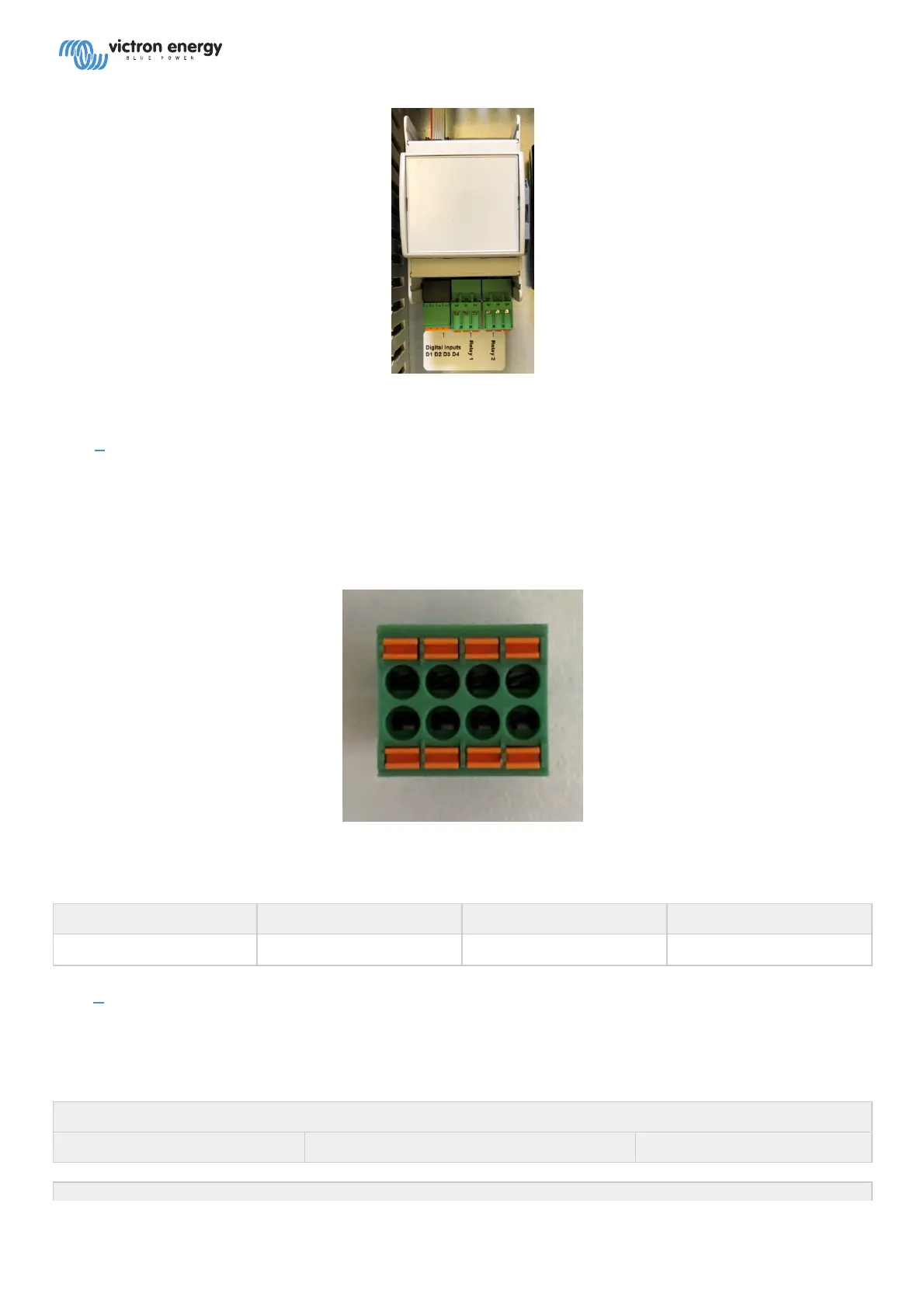
The terminal block has four pairs of two terminals:
The two on the left are digital input one (open or short them), the next two are digital input 2, and-so-forth. Where
upper row is signal and lower row is GND for all four inputs.
D1 D2 D3 D4
GND GND GND GND
2.4.3. # Relays
Relay 1 can be used for auto-starting a generator, an alarm relay, and as a free to use remotely operable relay via the
graphical interface. Relay 2 can be operated via a selection from graphical interface, but not used with the built in
autostart generator or alarm relay features.
Relay 1
NO COM NC
 Loading...