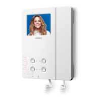
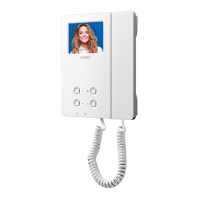
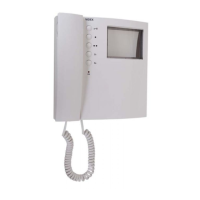
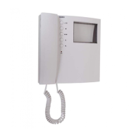
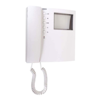
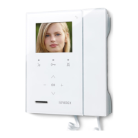
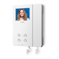
Art.6276 3.5" colour display videophone
TO SET THE VIDEO MODE AND TERMINATION
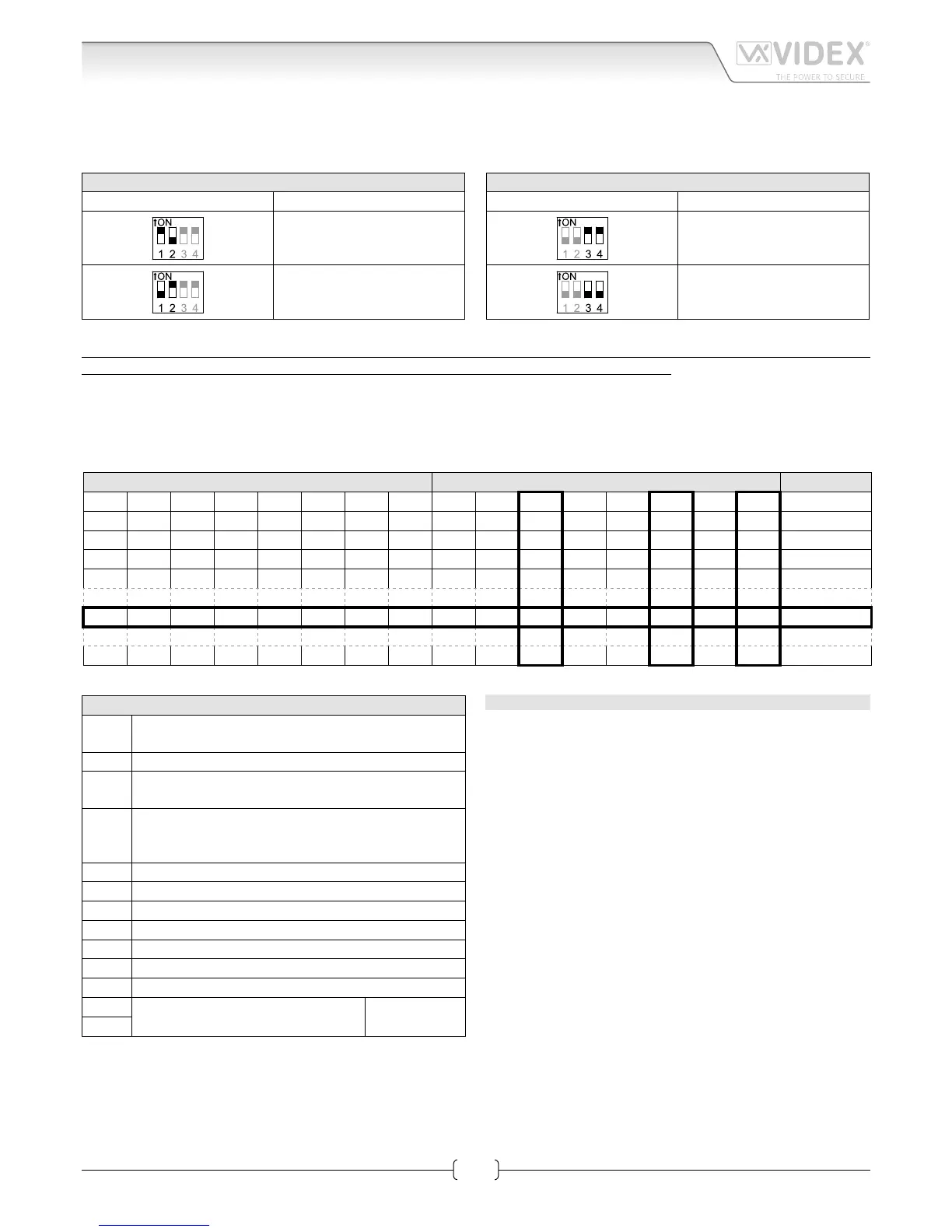
The videophone can operate with either composite video signal (coax cable) or balanced video signal (two wires). Switches 1 & 2 of
DSW2 are used to set video mode while switches 3 & 4 are for video termination.
VIDEO MODE DSW2
Switches 1,2 Mode
Coax
Balanced
75 OHM VIDEO TERMINATION DSW2
Switches 3,4 Termination
Enabled
Disabled
Switches 3 and 4 adjust the video signal impedance. when using more than one videomonitor in parallel (without a video
splitter) put both switches in the OFF position on all but the last videomonitor (end of line).
VIDEOMONITOR/INTERCOM ADDRESS, VIDEO MODE AND TERMINATION SETUP DSW1
Each intercom is addressed in binary (PHONE ID) using the 8 way dipswitches located on the rear of the unit. Each switch corre-
sponds to one bit which can have a value 0 (OFF) or 1 (ON). Each bit corresponds to a decimal weight depending on the position:
Switch 1 = decimal 1, 2=2, 3=4, 4=8, 5=16, 6=32, 7=64, 8=128. I.E. to set the address 37, put switches 1, 3 and 6 on (1+4+32=37).
SWITCHES DECIMAL WEIGHT ADDRESS
8 7 6 5 4 3 2 1 128 64 32 16 8 4 2 1
OFF OFF OFF OFF OFF OFF OFF ON 0 0 0 0 0 0 0 1 1
OFF OFF OFF OFF OFF OFF ON OFF 0 0 0 0 0 0 1 0 2
OFF OFF OFF OFF OFF OFF ON ON 0 0 0 0 0 0 1 1 3
OFF OFF OFF OFF OFF ON OFF OFF 0 0 0 0 0 1 0 0 4
OFF OFF ON OFF OFF ON OFF ON 0 0 1 0 0 1 0 1 37
ON OFF ON ON OFF ON OFF OFF 1 0 1 1 0 1 0 0 180
CONNECTION TERMINALS SIGNALS
+VD
12Vdc output to supply coax video distributor
Art.894N
+20 Video power supply 17÷20Vdc
V1
Balanced video signal V1 sync. (balanced video signal
mode)
V/V2
Balanced video signal V2 sync. (balanced video signal
mode)
Composite video signal (coax video signal mode)
GNDV Video power supply ground reference
L BUS line
– BUS line ground reference
LB Local bell input (active low)
AL Alarm input (active low)
DOL 12Vdc input to supply Aux LED
EXTC Call tone output for extension sounder (Art.512A)
SW
Service button connection
Max 24 Vdc
50mA
SW
TECHNICAL SPECIFICATION
Working Voltage: 17÷20Vdc
Power Consumption: 200mA during a call
120mA during a conversation
Working Temperature: -10°C +50°C


 To Next Page