Fig. 5
Abb. 5
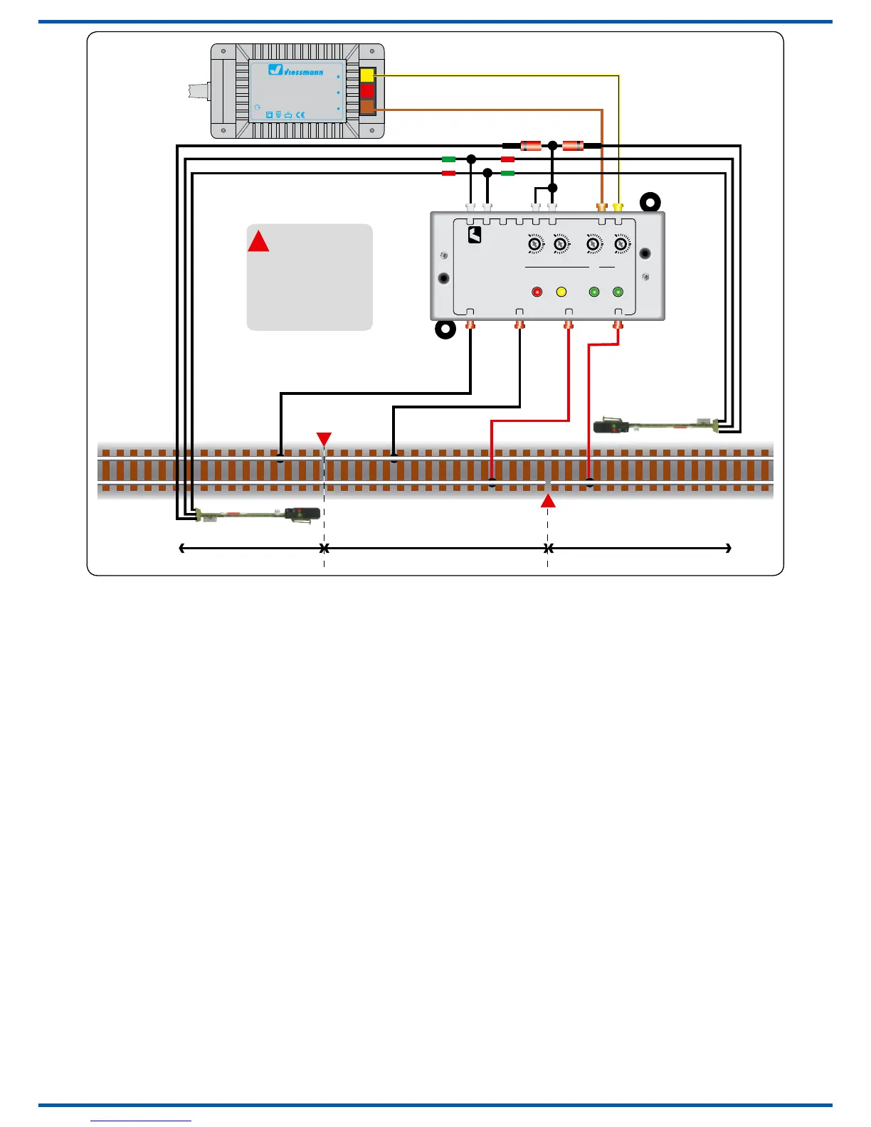
Anschluss mit Signalen
Für den Betrieb mit Lichtsignalen (z. B. Art-Nr.
4011) schließen Sie die Pendelzugsteuerung ge-
mäß Abb. 5 an. Beachten Sie auch die Hinweise
in Abb. 3!
Anschluss für Teilautomatikbetrieb
Abb. 6 zeigt den Aufbau für Teilautomatikbetrieb.
Mit dem Schalter (z. B. Art.-Nr. 6835 oder 5550)
erfolgt die Umschaltung zwischen Vollautomatik
(selbstständiges Pendeln gemäß Zeiteinstellung)
oder Teilautomatik (manueller Abfahrbefehl per
Taster). Als Taster eignet sich z. B. Art.-Nr. 5547.
Verbindung der Pendelzugstrecke mit
weiteren Gleisanlagen
Wenn eine Verbindung zwischen der Pendelstre-
cke und dem Rest der Gleisanlage hergestellt
werden soll, so ist diese Verbindung elektrisch
beidseitig zu isolieren. Es ist sicherzustellen, dass
der Zug keinen Kurzschluss zwischen Pendelstre-
cke und der weiteren Gleisanlage verursachen
kann. Hier hilft ein Übergangsabschnitt, in wel-
chen der Zug zunächst einfährt. Sobald der Zug
komplett im Übergangsabschnitt ist, wird dessen
Stromversorgung auf den Zielgleisbereich umge-
schaltet.
Connection of signals
For the use with colour light signals (e. g. item-No.
4011), connect the control module 5214 as shown
in g. 5. Observe the additional hints in g. 3.
Connection for semi-automatic
operation
See g. 6 for the setup for manual operation. The
switch (e. g. item-No. 6835 or 5550) enables the
modi full automatic or semi automatic (manual
start of the trains). For the push button the item-
No. 5547 is recommended.
Connection of the commuter train track
with further railway tracks
If you want to make a track connection between
the commuter train track and the rest of your lay-
out, you have to make a double-side rail insula-
tion. You have to take care that no short circuit
between the commuter train track and the rest of
your layout can occure. To ensure this, it´s a good
idea to make a transition section. When the train
is completely in it, you must connect the power
supply for this section to the destination track.
Dieses Symbol
neben dem Gleis
kennzeichnet eine
Trennstelle.
This sign beside
the track indicates
a track insulation.