91
5793 309 - 05
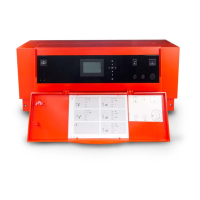
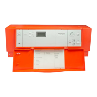
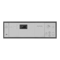
Vitotronic 100, GC1B / Vitotronic 300-K, MW1B Installation and Service
Checking Actuators and Sensors at the Vitotronic 300-K
Commissioning
The following relay outputs can be controlled subject to the system equipment level:
Display Explanation
“All actuators” OFF All actuators have been switched off.
“Output 20” ON Output 20 enabled.
“Output 52” Open -
“Output 52” Neutral -
“Output 52” Closed -
“DHW tank prim pump” ON Output for circulation pump for DHW tank heating enabled.
“DHW circ pump” ON Output for DHW recirculation pump enabled.
“Output 29” ON Output 29 enabled.
“Central fault mess.” ON -
“Htg circ pump HC2” ON Output heating circuit pump enabled (heating circuit with mixing valve M2).
“Mixing valve HC2” Open Output “Mixing valve open” enabled (heating circuit with mixing valve M2).
“Mixing valve HC2” Closed Output “Mixing valve closed” enabled (heating circuit with mixing valve M2).
“Htg circ pump HC3” ON Output heating circuit pump enabled (heating circuit with mixing valve M3).
“Mixing valve HC3” Open “Mixing valve open” enabled (heating circuit with mixing valve M3).
“Mixing valve HC3” Closed Output “Mixing valve open” enabled (heating circuit with mixing valve M3).
“EA1 output 1” ON
Contact “P - S” on plug aBJ for extension EA1 closed.
“AM1 output 1” ON Output enabled.
“AM1 output 2” ON Output enabled.
“Solar circuit pump” ON
Output for solar circuit pump sF at solar control module, type SM1, enabled.
“Solar circ pmp min” ON
Output for solar circuit pump sF at solar control module, type SM1, switched
to minimum speed.
“Solar circ pmp max” ON
Output for solar circuit pump sF at solar control module, type SM1, switched
to maximum speed.
“SM1 output 22” ON
Output sS at solar control module, type SM1, enabled.
1. Press OK and
simultaneously for approx. 4 sec.
2. “Actuator test”
Carrying out a relay test
Checking sensors
1. Press OK and
simultaneously for approx. 4 sec.
2. “Diagnosis”
3. Select group (see overview on page 97).
4. Scan actual temperature of the relevant sensor.
 Loading...