41
5285 429 - 03
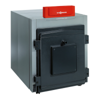
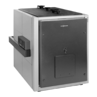
Vitorond 200, VD2 Series 320 to 1080 Installation
Appendix
Technical Data (continued)
hni
al Dat
oil
r Mod
l
D
3
3
4
3
1
oil
r
onn
tion
Bo
er supp
y
n
r
turn
n
afety supply
n
2
2
2
2
2
2
2
2
2
2
2
afety return
n
2
2
2
2
2
2
2
2
2
2
2
ra
n va
v
n
eatin
sur
ace are
F
ue
as s
e
2
2
7
15.8
18.2
212
1
.7
2
2
21.5
254
23.6
274
25.5
2
27.5
17
2
.5
31.5
5
33.3
35.3
Wat
r
2
2
.1
10.1
2
11.2
1
12.2
42
13.2
5
14.2
5
15.3
16.3
.7
17.4
18.4
2
1
.4
lue
a
-
emperature
ross
F
º
74
1
0
74
1
0
74
1
0
74
1
0
74
1
0
74
1
0
74
1
0
74
1
0
74
1
0)
1
5
1
5
- F
ue
as mass
low rat
s.
/
1
5
0
5
725
54
841
2
1
44
2
7
1060
2
1
1180
2
7
1314
1
1450
527
1600
25
1735
4277
1
40
With minimum heatin
input and a 2-sta
e burner (operation of sta
e 1
-
emperature
F
º
2
130
2
130
2
130
2
130
2
130
2
130
2
130
2
130
2
130
275
135
275
135
- F
ue
as mass
low rat
at
m
n.
nput rate
s.
/
71
322
42
382
74
442
1
503
241
563
634
552
704
7
785
7
865
211
57
2
4
1086
Bo
er stan
y
o
a
on
max.
eat
n
nput an
ot
ater supp
y an
return temps. o
67
140°F
75 / 60°
.4
.
.
.
2
.
1
.2
.2
.2
.2
.2
.2
ent pipe collar
ut
r
8
n.
mm
2
300
2
300
2
300
2
300
2
300
2
300
2
300
2
300
2
300
2
300
2
300
lue
as
s
stan
- at upper en
rated inpu
w.c.
m
ar
.2
0.5
.
5
0.
.51
.3
.
7
1.7
.75
1.
.
2.1
.1
2.8
.
3.
.
4.
.
4.5
2.2
5.8
Required
lue
ra
t
ate
ory
a
w.c
0
0
0
0
0
0
0
0
0
0
0
os
t
ve pressur
ate
ory II
a
w.c
2
0.08
2
0.08
2
0.08
2
0.08
2
0.08
2
0.08
2
0.08
2
0.08
2
0.08
2
0.08
2
0.08
*5
Connections for boiler connection kit (standard equipment).
*6
Combustion results are based on 13.0% CO
2
with fuel oil #2 and 10% CO
2
with natural gas, as well as a system
supply temperature of 167°F (75°C), and a system return temperature of 140°F (60°C).
*7
Measured flue gas temperature with a combustion air temperature of 68°F (20°C) and a boiler water temperature
of 176°F (80°C).
*8
Vent pipe collar diameter does not automatically indicate vent/chimney size. See page 13 for details.
The combustion burner head material must be suitable for temperatures of at least 932°F (500°C).
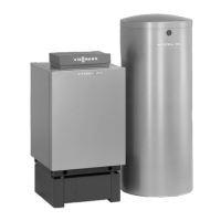
For information regarding other Viessmann System Technology componentry, please reference documentation
of respective product.