18
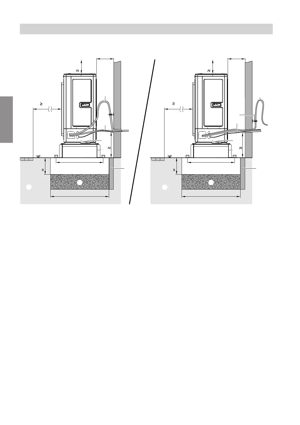
Floorstanding installation with support; line entry above ground level
3000
K
L
A
b
300
C
E
600
730
B
G
550
3000
K
L
A
b
300
C
E
600
730
F
B
G
550
H
F
H
200
200
M M
Fig. 11
b Wall clearance for cable entry above ground level:
See "Minimum clearances".
A
Supports for floorstanding installation
B
Openings in the base plate for free drainage of
condensate:
Do not seal the openings.
C
Foundation strips
E
Frost protection for foundations (compacted
crushed stone, e.g. 0 to 32/56 mm); thickness of
layer subject to local requirements and building
regulations
F
Indoor/outdoor unit connecting cables and outdoor
unit power cable:
Route the cables free of strain.
G
Pipe clips with EPDM lining
H
Pipe bend for vibration compensation in the hot
gas line:
We particularly recommend installing the vibration
bend on lines of < 5 m.
K
Pathway, patio
L
Ground
M
Flexible separating layer between the foundations
and the building
Sound insulation and vibration isolation
For further information on vibration compensation, see
chapter "Sound insulation and vibration isolation" on
page 26.
Installation sequence
Installing the outdoor unit (cont.)
6199585
Installation
 Loading...