10
Sequence Responsibility Page
Installation
1 Check system requirements. Heating contractor/IT expert 7
2 Fit wall mounting bracket for Vitoconnect 100. Heating contractor 11
3 Connect Vitoconnect 100 to heat source. Heating contractor 12
4 Insert Vitoconnect 100 into wall mounting bracket. Heating contractor 11
5 Connect power supply. Heating contractor 12
Commissioning
6 Check network settings. IT expert 14
7 Register user and set up heating system. Heating contractor/system user 14
■
Operation with ViCare app
■
Operation with Vitotrol Plus app
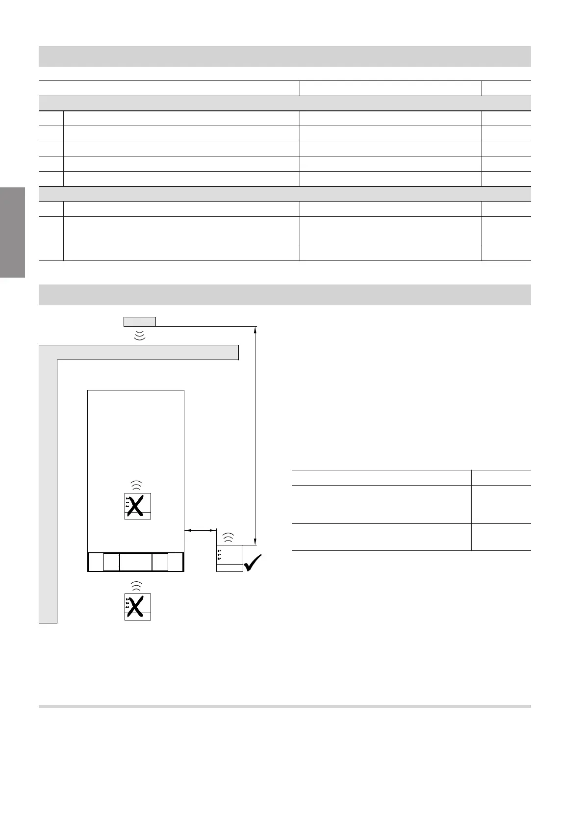
Installation location
Fig. 2 Sample illustration with wall mounted boiler
A
To ensure a good WLAN connection, keep the dis-
tance between the Vitoconnect 100 and the WLAN
router as short as possible.
Installation type: wall mounting
■
Distance to heat source: minimum 0.3 m
■
Standard socket 230 V/50 Hz, max. 1 m lateral dis-
tance to installation site
■
Internet access with adequate WLAN signal
Note
The WLAN signal strength can be increased with
commercially available WLAN repeaters.
Note
When selecting the installation site, bear in mind the
length of the connecting cables (standard delivery).
Connecting cables/leads Length
Connecting lead Optolink/USB for con-
necting the Vitoconnect 100 to the boiler
control unit
3 m
Plug-in power supply unit with power ca-
ble
1 m
Range
The range of WLAN connections may be reduced by
walls, ceilings and interior fixtures. These weaken the
WLAN signal and can cause poor reception.
Installation sequence
Sequence overview
5785 665 GB
Installation