9
Inial Setup
Wall Mounng
Refer to the table below for the standard dimensions for wall mount kits.
NOTE: For use only with a UL cered wall mount kit/bracket. To obtain a wall-
mounng kit or height adjustment base, contact ViewSonic® or your
local dealer.
Maximum
Loading
Hole paern
(W x H)
Interface Pad
(W x H x D)
Pad Hole
Screw Specicaon
& Quanty
23.7 kg 200 x 100 mm 235 x 135 x 2 mm Ø 8 mm
M6 x 12 mm
4 pieces
113.6 400 x 200 mm 435 x 235 x 2 mm Ø 8 mm
M6 x 12 mm
4 pieces
NOTE: Wall mount kits are sold separately.
1. Turn o the device and disconnect all cables.
2. Place the device on a at, stable surface with the screen facing down.
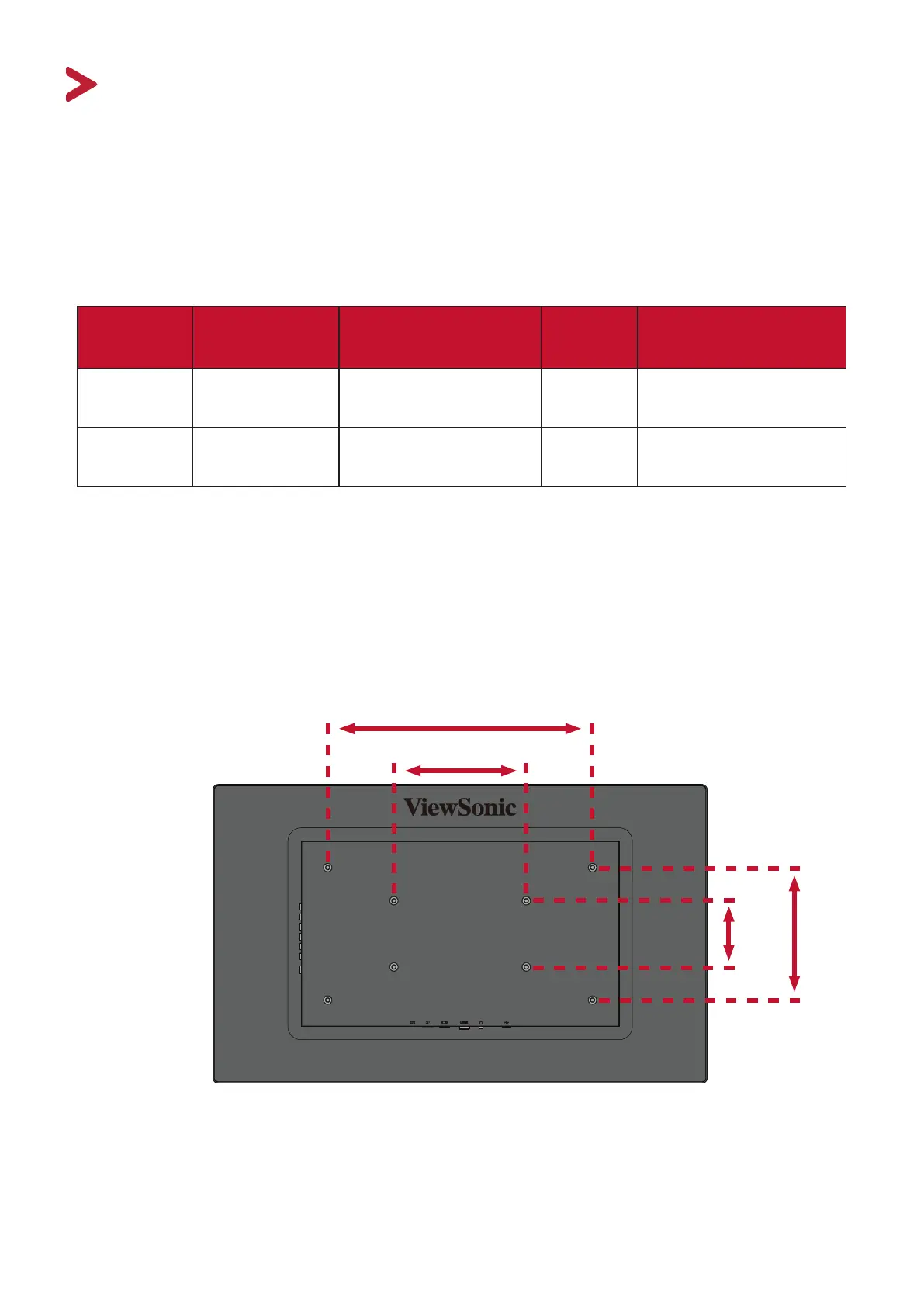
3. Aach the mounng bracket to the VESA mounng holes at the rear of the
monitor. Then secure it with four (4) screws (M6 x 12 mm).
200 mm
4. Follow the instrucons that come with the wall mounng kit to mount the
monitor onto the wall.
400 mm
100 mm
200 mm