ViewSonic Corporation Confidential - Do Not Copy VA702-1_VA702b-1
23
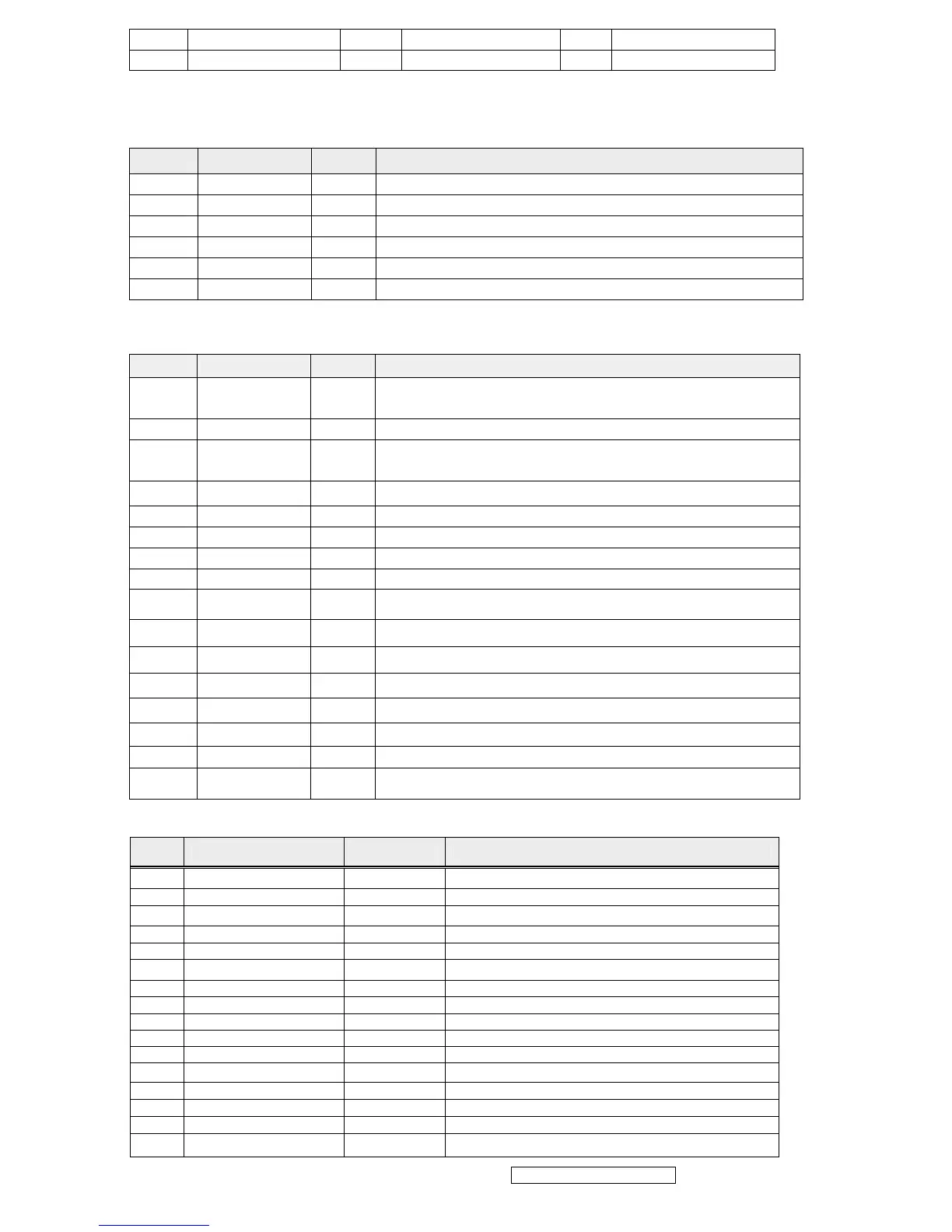
4 NC 9 +5V(from PC) 14 VSYNC
5 Cable Detect 10 GND 15 Data clock line (SCL)
7. Key Parts Pin Assignment
7.1 IC802 (TOP246Y, Power Control IC)
Pin Symbol I/O Description
1 C I Control
2 L I Line Sense
3 X I External Current Limit
4 S O Source of MOSFET(GND)
5 F I Frequency
6 D I Drain of MOSFET
7.2 IC501 (OZ9910G, CCFL inverter controller IC)
Pin No. Symbol I/O Description
1 NDRV4 O
Bottom MOSFET gate drive output in dual forward
converter
2 PGND High-current power ground
3 NDRV2 O
Bottom MOSFET gate drive output in dual forward
converter
4 GNDA Low-current signal ground
5 CT I Timing capacitor of high frequency oscillator
6 LCT I Timing capacitor of set LPWM frequency
7 ADJ I Control command input –DC
8 ENA I Enable input
9 VSEN
I
Voltage sense feedback
10 CMP_SST
I
Soft start and loop compensation capacitor
11 ISEN
I
Current sense feedback
12 VREF
O
Reference voltage output
13 VIN
I
Supply voltage for IC
14 HSB
I
High side driver buffer output
15 PDRV3
O
Top MOSFET gate drive output in dual forward converter
16 PDRV1
O
Top MOSFET gate drive output in dual forward converter
7.3 U104 (TSU16AK)
Pin Symbol I/O Description
1 LVBOM O
B-Link Negative LVDS Differential Data
2 GND Ground
3 BYPASS
For External Bypass Capacitor
4 NC Not connected
5 NC Not connected
6 BUSTYPE IN Low : Serial bus; High : Direct bus
7 NC Not connected
8 NC Not connected
9 NC Not connected
10 GND Ground
11 VDDP O Digital Output Power
12 NC Not connected
13 NC Not connected
14 NC Not connected
15 NC Not connected
16 NC Not connected