EasyManua.ls Logo

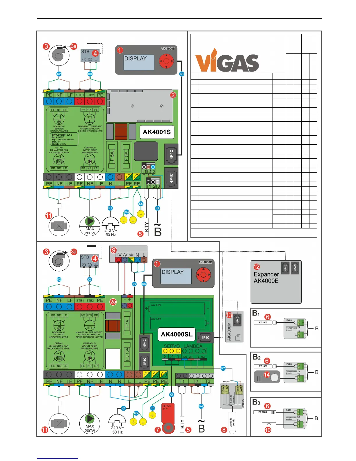
VIGAS 40 Lambda Control - ELECTRIC SCHEME DETAILS; Component Identification and Wiring

Default Icon
36 pages
Print Icon
To Next Page IconTo Next Page
To Previous Page IconTo Previous Page
Loading...
32
Gasifying boiler Vigas
20. ELECTRIC SCHEME
ELECTRIC SCHEME
VIGAS
VIGAS
LC
16,25,40
29UD kW
60,80,100 kW
16,25,40 kW
60,80,100 kW
No
Description Code
1
AK 4000D Display
4001
2
AK 4001S Power board
4002
– –
2a
AK 4000SL Lambda board
4003 – –
3 Fan
0514
2
2
0516 –
–
3a
Condenser
0515
2
2
4
STB fuse
3029
5 Thermometer type KTY 3026
6 Gas sensortype PT 1000 3027
7 Servo Belimo 3008 – –
8 Lambda sensor 3009 – –
9
Supply RS 25 - 12
4004
–
–
10
Accumulator thermometer
type KTY (4m)
3032
11
Discharge fan
0507
–
–
0508
12
Expander AK4000
SET
13
Memory modul AK4000M
4007
14
Indoor thermostat 3030
K1
Connector 3025
K2
Fan wire
3010
–
–
3011 –
–
K3
Wire set for STB fuse
3015
K4
Thermometer connection modul
3022
–
–
3023 –
–
K5
Main ground wire 3018
K5a
Ground wire for the control cover panel 3019
K6
Communication wire AK40000(4P4C 0,4m)
4006
K7
Lambda sensor connection modul
3024
–
–
–
3024
–
–
–
K8
Wire for servo-unit 3013 – –
K9
Wire set for power supply RS 25 - 12 4005 – –
standard,
extra cost, – not available,
only for 40, 40LC,
only for 100, 100LC (2psc)