7
Gasifying boiler VIGAS
3. DESCRIPTION OF AK4000 CONTROL
3.1 SAFETY INSTRUCTIONS
Please check the protective cover panels before you plug-in the power lead
Avoid any contact of the power lead with hot parts of the boiler (e.g. smoke flue).
Make sure that upper insulation under the panel remains dry (risk of short circuit if damp)
Do not put any stress on power lead.
Always disconnect the power lead when new electrical components are being connected to the
boiler (eg indoor room thermostat, discharge fan, circulation pump...)
Do not remove the protective cover panels, and particularly the fan cover panel, when the boiler is
in operation.
Check if the voltage displayed on the label is same as your distribution network.
Always keep to the terms of use
3.2 CONNECTION TO THE POWER SUPPLY
AK 4000 Control is an integral part of VIGAS boilers.
The control is connected when the power lead is plugged into a 220/230V power supply. The visual display
with basic image is active when the power lead is plugged-in (pic.4). Servo-flap used in VIGAS
Lambda Control
is set to basic position (pic.5).
3.3 SERVICE CONDITIONS
AK4000 Control is designed for operation within a temperature range from +5°C up to +45°C. The Control
cannot be used in a moist environment or in direct sunlight.
3.4 MAINTENANCE OF AK4000 CONTROL
Keep in a clean and dust free environment. Anti-static cloths or wet wipes are recommended to wipe-off
dust and impurities from metal covers and the control panel.
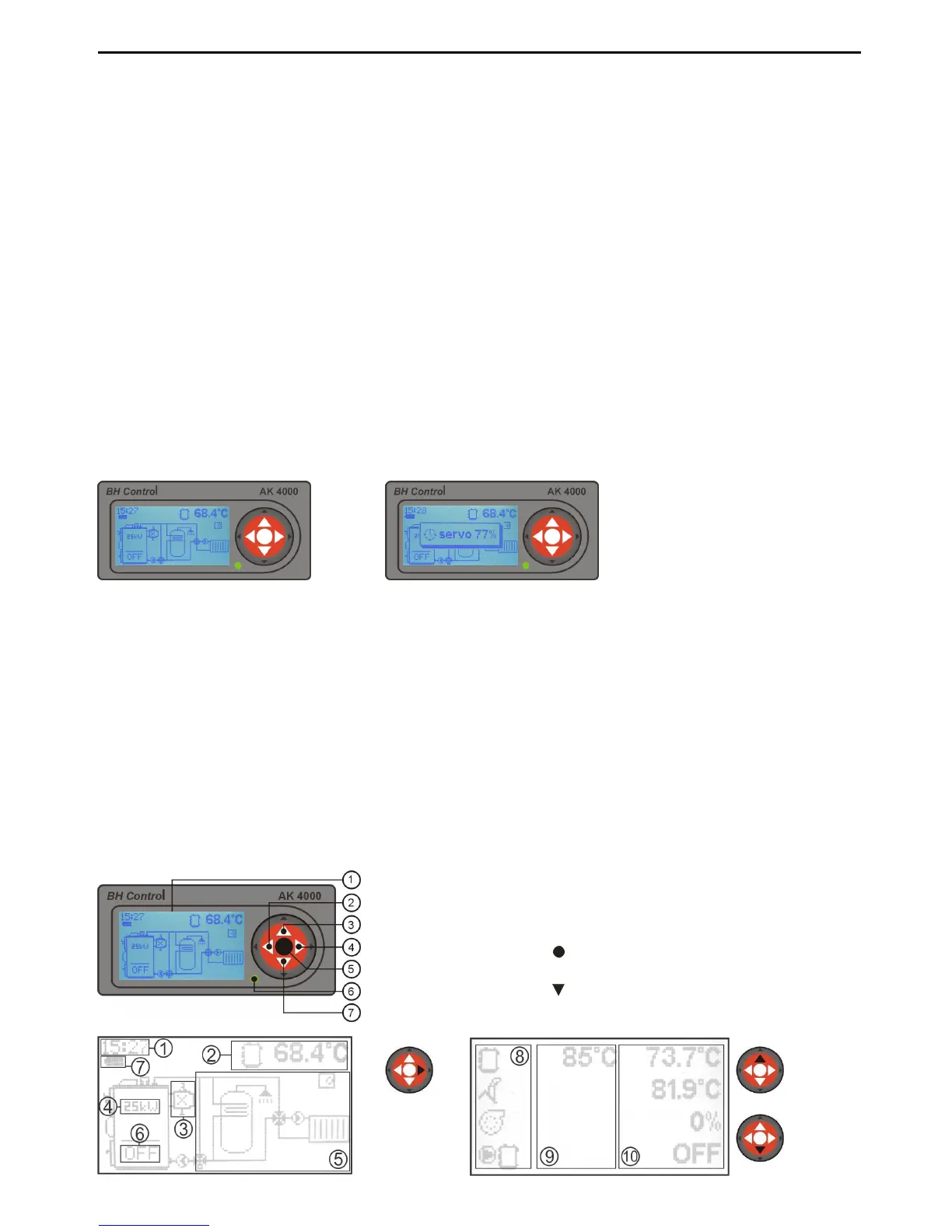
3.5 CONTROL PANEL
Part of the electronic control panel is equipped with buttons, visual display and schematics. Further
information is available in the following sections of this manual.
pic.
Pic.5
1. Graphic display 128 x 64 pix.
2. Button ◄ with functions, ENTER
3. Button▲ with functions
4. Button ► with functions, EXIT (ESC)
5. Button (ENTER) with functions
6. LED control (green - OK, red - ERROR)
7. Button switch functions
Pic.4