SECTION TSM 630 ISSUE J PAGE 5 OF 10
3. Place tapered installation sleeve on shaft. Coat rotor
shaft, tapered installation sleeve, and O-ring in the
inside diameter of cartridge seal sleeve with a generous
amount of light oil. Refer to Figure 7.
4. Slide cartridge seal over installation sleeve on shaft
until it contacts the seal chamber face. Remove tapered
installation sleeve from shaft.
5. Place pair of half round rings in groove on shaft and turn
bearing housing assembly into bracket. There are no
half round rings on the G, H and HL size pumps.
6. Put lockwasher and locknut on shaft. Tighten locknut
and bend one tang of lockwasher into slot of locknut.
Note: G size has no lockwasher.
7. Adjust pump end clearance as in Thrust Bearing
Adjustment page 8.
8. Insert gland capscrews and secure gland to bracket face.
NOTE: turn shaft several turns while gland is loose to
center seal; then tighten gland tight enough to compress
gasket. Tighten only enough to contain leakage and not
to distort gland.
9. Lock cartridge seal drive collar to shaft and remove or turn
centering clips out of the way so as to clear the drive collar.
10. Turn shaft by hand or jog motor to check drive collar for
runout.
11. Connect suckback or flush line or vent stuffing box seals
without flush line until liquid is present on start up.
NOTE: For maximum seal life, suckback or flush line
should be used.
FIGURE 7
TAPERED INSTALLATION SLEEVE
COAT ROTOR SHAFT, TAPERED INSTALLATION
SLEEVE AND INNER DIAMETER OF MECHANICAL
SEAL WITH LIGHT OIL BEFORE ASSEMBLY.
SHAFT
DANGER !
Before starting pump, be sure all drive equipment
guards are in place.
Failure to properly mount guards may result in
serious injury or death.
ASSEMBLY
COMPONENT MECHANICAL SEAL
MODELS:
G, H, HL, AK, AL, K, KK, L, LQ, AND LL4124A CAST IRON
L, LQ AND LL 4124AE CAST IRON
H, HL, K, KK, L, LQ, AND LL4126A DUCTILE IRON
H, HL, K, KK, LQ, AND LL4123A STEEL EXTERNALS
H, HL, K, KK, LQ AND LL4127A STAINLESS STEEL
This seal type can be installed as an alternate to the cartridge
mechanical seal. The seal is setscrew driven, is simple to
install and good performance will result if care is taken during
installation.
For complete pump disassembly and assembly see pages
6 and 7. For Step 6, disassembly, remove the appropriate
nuts, capscrews, seal holder and seal seat. Remove the pipe
plug in the bracket and loosen the setscrews holding the
mechanical seal rotary member to the shaft. This must be
done before the rotor is removed to avoid damage to the seal
and the rotor shaft.
The following steps are for mechanical seal assembly.
1. Clean rotor shaft and seal housing bore. Make sure
they are free of dirt, grit and scratches. Gently radius
leading edge of the shaft diameter over which seal is to
be placed.
Never touch mechanical seal faces with anything except
clean hands or clean cloth. Minute particles can scratch
the seal faces and cause leakage.
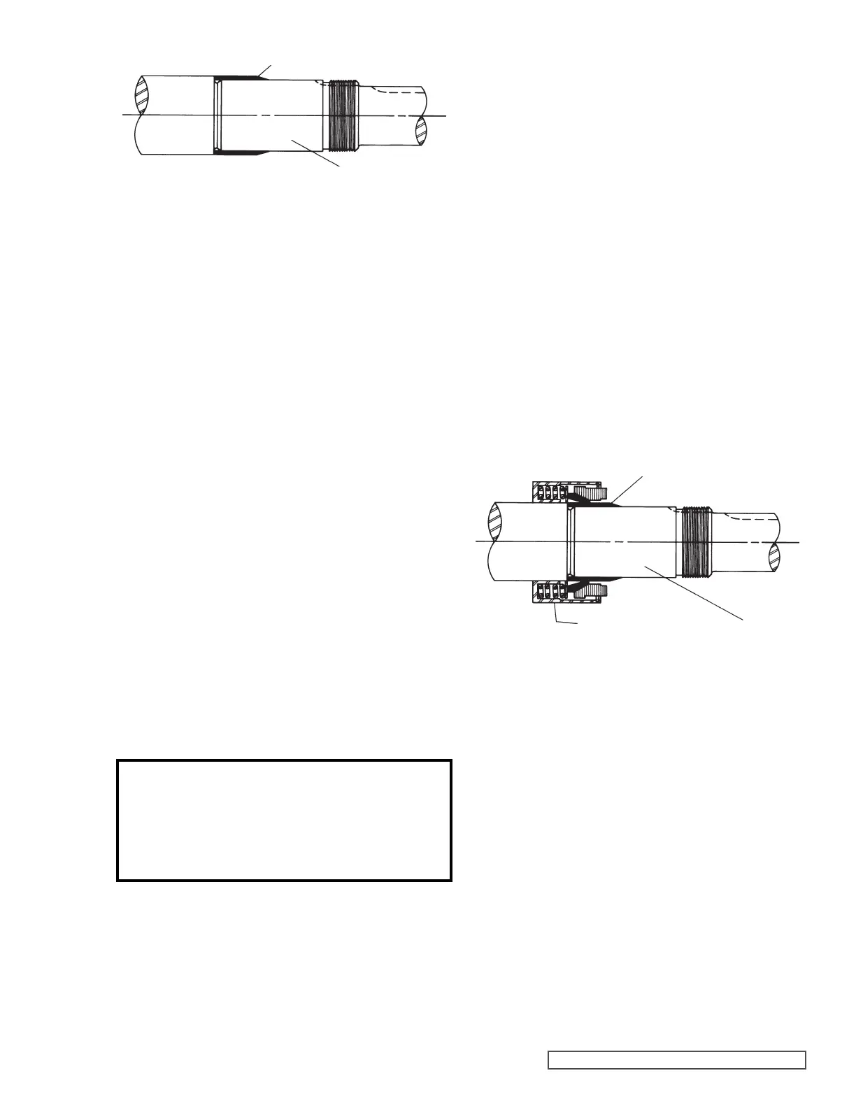
2. Place tapered installation sleeve on the shaft. Coat
tapered sleeve and inside of the rotary member
with a generous quantity of light oil. Grease is not
recommended. Start rotary member on shaft and over
tapered sleeve. Refer to Figure 8.
FIGURE 8
TAPERED INSTALLATION SLEEVE
SHAFT
MECHANICAL SEAL
ROTARY MEMBER
3. Move rotary member so setscrews are directly below seal
access holes on side of bracket. Tighten all setscrews
securely to shaft. Some seals are equipped with holding
clips which compress the seal springs. Remove holding
clips to release springs after seal is installed on shaft.
4. FOR “O-RING” GASKET TYPE MECHANICAL SEAL
SEAT: Lubricate outer diameter of O-Ring seal gasket
with oil. Flush sealing faces of both rotary member and
seal seat with oil and press seal seat in to bore until back,
unlapped face, is flush with bore. Install seal holder,
capscrews, and nuts and tighten securely. Remove
tapered installation sleeve.
FOR “CLAMPED-IN” TYPE MECHANICAL SEAL
SEAT: Flush sealing faces of both rotary member and
seal seat with oil and install seal seat and seat gasket
over end of shaft against machined bracket face. Install
other seal gasket, seal holder, capscrews, and nuts and
tighten securely. Remove tapered installation sleeve.
5. Connect suckback or flush line or vent stuffing box for
seals without flush line until liquid is present on start up.
NOTE: For maximum seal life, suckback or flush line
should be used.