SECTION TSM 630 ISSUE J PAGE 4 OF 10
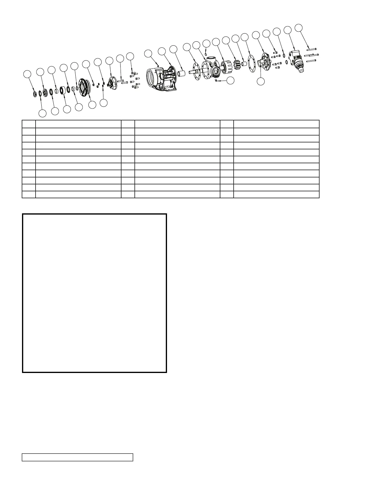
FIGURE 6 - EXPLODED VIEW SERIES 4123A, 4124A, 4124AE, 4126A, AND 4127A MODELS
ITEM NAME OF PART ITEM NAME OF PART ITEM NAME OF PART
1 Locknut 17 Capscrews, Seal Gland 37 Idler and Bushing Assembly
2 Lockwasher (Not G) 19 Seal (Cartridge Seal Shown) 38 Idler Bushing
3 End Cap 25 Bracket Bushing 39 Idler Pin
4 Bearing Spacer Collar (Outer) 27 Bracket and Bushing Assembly 40 Head and Idler Pin Assembly
5 Lip Seal 28 Capscrew for Bracket 43 Capscrew for Head
6 Ball Bearing 29 Bracket Gasket 45 Relief Valve Gasket
7 Bearing Housing 30 Pipe Plug 46 Capscrew for Valve
8 Bearing Spacer Collar (Inner) 31 Casing (Tapped or Flanged) 47 Internal Relief Valve
11 Ring, Half Round (Not G, H, HL) 35 Head Gasket 50 Seal Gland Washers
12 Grease Fitting 36 Rotor and Shaft Assembly 50A Seal Gland Lock Washers
REPAIR: MODELS G, H, HL, AK, AL, K, KK, L, LQ & LL
CARTRIDGE MECHANICAL SEAL PUMPS
CARTRIDGE MECHANICAL
SEAL REPLACEMENT
CARTRIDGE MECHANICAL
SEAL REMOVAL
MODELS:
G, H, HL, AK, AL, K, KK, L, LQ, & LL4124A CAST IRON
L, LQ, & LL4124AE CAST IRON
H, HL, K, KK, L, LQ & LL4126A DUCTILE IRON
H, HL, K, KK, LQ & LL4123A STEEL
H, HL, K, KK, LQ & LL4127A STAINLESS STEEL
1. Insert length of hardwood or brass through port opening
between rotor teeth to keep shaft from turning. Bend up
tang of lockwasher and with a spanner wrench, remove
locknut and lockwasher from shaft.
Note: G size has no lockwasher.
2. Loosen two set screws in the face of the bearing housing
and remove the bearing housing assembly from the
bracket.
3. Remove the pair of half round rings under the inner
spacer collar from the shaft. There are no half round
rings on the G, H and HL size pumps.
4. If suckback, flush or barrier fluid tubes are connected
to the seal gland, disconnect before removing seal.
Replace or turn centering clips to original position.
Loosen the set screws on the cartridge seal collar to free
the cartridge seal from the shaft. Remove the two gland
capscrews and slide cartridge seal out through bearing
housing opening.
1. NOTE: Burrs left on shaft can damage O-ring on seal
sleeve during installation. Inspect shaft for burrs and
remove any found with a fine grade of emery cloth.
2. Clean rotor shaft and face of seal chamber.
CARTRIDGE MECHANICAL
SEAL INSTALLATION
1
2
3
5
4
6
5
8
11
7
16
50A
50
19
17
28
27
12
25
29
30
30
31
36
37
38
35
39
40
43
45
47
46
DANGER !
Before opening any Viking pump liquid chamber
(pumping chamber, reservoir, relief valve
adjusting cap fitting, etc.) Be sure:
1. That any pressure in the chamber has been
completely vented through the suction or
discharge lines or other appropriate openings
or connections.
2. That the driving means (motor, turbine,
engine, etc.) has been “locked out” or made
non-operational so that it cannot be started
while work is being done on pump.
3. That you know what liquid the pump has been
handling and the precautions necessary to
safely handle the liquid. Obtain a material
safety data sheet (MSDS) for the liquid to be
sure these precautions are understood.
Failure to follow above listed precautionary
measures may result in serious injury or death.
For complete pump disassembly and assembly see
pages 6 and 7.